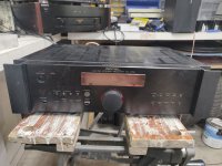
Yeah, just realized that I had not soldered the bottom pads of the output transistors on the channel I am struggling with. Did that. But I am lost on variable resiso position. resistor orientation. Because the variable resistors parallel each other, changine one changes the other. Orientation checks out for everything.
I think I will try 40 turns counter clockwise, to be sure they are backed out one way. Then give it 10 to the right on each to get them closer to the middle. I can't recall how many turns the items I put in are.
I think I will try 40 turns counter clockwise, to be sure they are backed out one way. Then give it 10 to the right on each to get them closer to the middle. I can't recall how many turns the items I put in are.
that didn't work. But turning clockwise all the way seems to be where I should start for vr1. And for vr2, it should give me high negative dc offset. It seems like it has wanted to stay more negative on the dc offset, and something seemed out of balance. R15 should be 3k, and the color bands check out, but it was 3.4k on the channel I am struggling with, whereas the functioning channel was reading 3k as expected. More investigating tomorrow.
Thanks for the input amplidude
Thanks for the input amplidude
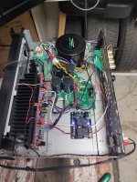
Ok, I've got a functioning amp that sounds very nice. My issue with the channel I was struggling with was I had an input transistor in backwards. I've never ever made a mistake like that working on cars.... Hehe. So got both channels sorted. I set dc offset to 2.5mv on each channel, and bias to 75ma on each channel. I will see how the amp feels after running for an extended period, and then toy with turning it up a bit. I believe 100ma is what the recommended setting is, is that correct?
I wired up a alps 40k pot for attenuation just because I can't have a gaping huge hole there with a giant knob that doesn't do anything. I need to figure out a button for the faceplate to power the unit on. I have a simple pushbutton, and will likely run it to an arduino to control the that turns the unit on when it is in standby, as well as a power indicator led, and perhaps a small lcd screen that can act as a vu meter or rail voltage ind, whatever. Anyway, I have a good amp it appears, and after listening for awhile I will come back and post my impressions vs the phase linear it just displaced, as well as the two honey badgers I have built (and love). Cracker and Cake being served up tonight!
I wired up a alps 40k pot for attenuation just because I can't have a gaping huge hole there with a giant knob that doesn't do anything. I need to figure out a button for the faceplate to power the unit on. I have a simple pushbutton, and will likely run it to an arduino to control the that turns the unit on when it is in standby, as well as a power indicator led, and perhaps a small lcd screen that can act as a vu meter or rail voltage ind, whatever. Anyway, I have a good amp it appears, and after listening for awhile I will come back and post my impressions vs the phase linear it just displaced, as well as the two honey badgers I have built (and love). Cracker and Cake being served up tonight!
Attachments
I'm glad you found the error, I have done that mistake several times too.
It's a great joy to think a project, source parts, tinkering and assembly, and then end up with something that actually works, and works well.
Regarding bias, some run them hot, others don't, theres alot of threads on that subject, if you have access to let's say arta you can adjust bias to meet lowest possible distortion.
Yeah, thanks for your help amplidude. I don't know the va rating of the transformer, it was not in the rotel service manual, and when I asked rotel, they politely directed me to the nearest tree and told me to start climbing. But, given that the receiver was a 100wpc 2 channel unit, I suspect it is underpowered. Rail voltages are at 56.2v.
It was a fun build though, and as it was super cheap, I think I am into it like $100, or $120, I'll just keepeasing around with it as a platform for arduino stuff, and whatever else sounds fun.
No arta,. Just an old analog scope and a multimeter.
It was a fun build though, and as it was super cheap, I think I am into it like $100, or $120, I'll just keepeasing around with it as a platform for arduino stuff, and whatever else sounds fun.
No arta,. Just an old analog scope and a multimeter.
I have done some listening to this now in a couple different systems.
System one uses a nad 1155 preamp and a pair of Polk rt55 bookshelf speakers on stands. Cd source. Listened to cracker, cake, beethoven 9th, nirvana, buena vista social club, beastie boys, etc... This is the basement setup. In this configuration the amp rocks. I love it. Full bass, excellent soundstage, nice clear highs, but not bright at all. I wonder if reading other people's thoughts that highs are a little subdued impacts my perception as sometimes I think highs are subdued, but I really like the amp here. Sounds great. This is where it has spent nearly all of its time since becoming operational.
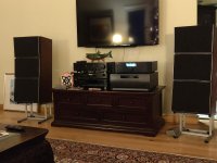
Moved it upstairs to the main living room where the system is a bit different. Cd optical to a Sony ta-e1000esd preamp. Speakers are large bang and olufsen ms150. Regular duty amp here is a honey badger in an arcam receiver case with large power supply. In this setting the amp lacks oomph for lack of a better word. It just doesn't have the power to push the ms150 power sponges. It sounds nice at lower volumes, similar to how it sounds in the basement, but it starts to sound muddy and muffled as I turn the volume knob up.
My thought is... The amp is being held back by the small transformer. Transformer is a unit from a rotel rx1052, which is a 100x2 receiver. I have 40,000uf in a capacitor bank pilfered from the arcam. The supply is straight from the rectifier to the caps and out for each side, not crc, or clc. And provides 59v rails. I don't hear clipping it just starts to sound soft. I think I will remove the cover, crank it up and see if the voltage is sagging significantly. I suspect it is. Regardless if I make changes to this or not, it sounds wonderful in the basement, and I will be happy with it if I choose to leave it down there.
I have some more stuff coming for it, I ordered up a futaba vfd display, and will see if I can find some fun stuff to do with it in all that space in the case, maybe vu meter, rail voltage monitor, proper standby on off switch on the face...
System one uses a nad 1155 preamp and a pair of Polk rt55 bookshelf speakers on stands. Cd source. Listened to cracker, cake, beethoven 9th, nirvana, buena vista social club, beastie boys, etc... This is the basement setup. In this configuration the amp rocks. I love it. Full bass, excellent soundstage, nice clear highs, but not bright at all. I wonder if reading other people's thoughts that highs are a little subdued impacts my perception as sometimes I think highs are subdued, but I really like the amp here. Sounds great. This is where it has spent nearly all of its time since becoming operational.
Moved it upstairs to the main living room where the system is a bit different. Cd optical to a Sony ta-e1000esd preamp. Speakers are large bang and olufsen ms150. Regular duty amp here is a honey badger in an arcam receiver case with large power supply. In this setting the amp lacks oomph for lack of a better word. It just doesn't have the power to push the ms150 power sponges. It sounds nice at lower volumes, similar to how it sounds in the basement, but it starts to sound muddy and muffled as I turn the volume knob up.
My thought is... The amp is being held back by the small transformer. Transformer is a unit from a rotel rx1052, which is a 100x2 receiver. I have 40,000uf in a capacitor bank pilfered from the arcam. The supply is straight from the rectifier to the caps and out for each side, not crc, or clc. And provides 59v rails. I don't hear clipping it just starts to sound soft. I think I will remove the cover, crank it up and see if the voltage is sagging significantly. I suspect it is. Regardless if I make changes to this or not, it sounds wonderful in the basement, and I will be happy with it if I choose to leave it down there.
I have some more stuff coming for it, I ordered up a futaba vfd display, and will see if I can find some fun stuff to do with it in all that space in the case, maybe vu meter, rail voltage monitor, proper standby on off switch on the face...
Last edited:
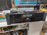
I don't know what I was listening too in my last review, but after a long hiatus, the gb150d is back in my main system upstairs in the living room, and we've been listening to it all day today. It is very good. It's true that higher frequencies are not as pronounced as the honey badger, but I've been really enjoying it today. It really shined with Chick Corea's piano on his Acoustik band album. It has been my garage workbench near field listening amp for months now, and it is great down there. But it does have the power to push the big ms150 power sponge speakers in the living to well past moderate levels (again, I think the stock rotel transformer doesn't have quite the juice the amp really requires to reach full potential).
I did manage to get a display fitted, so it is a little more presentable...
Very pleased with the amp. Also, I can't believe I actually got the display to work properly.
I did manage to get a display fitted, so it is a little more presentable...
Very pleased with the amp. Also, I can't believe I actually got the display to work properly.
Attachments
Well, I didn’t think the thermal control in Greg’s design was bad, but I certainly improved on it when I redesigned for my clone and with a far better pcb layout than his. (probably why he deleted my posts from his forum and locked the thread without any explanation!).
Hi Bigun,
I have build my GB300D maybe 10 years ago or so and at the time did a number of tweaks to improve the sound. As you may know, the 300 already boasts improvements such as a bootstrapped cascode on the lpt's (hence no modulation of the collector voltage) and also the zener mod.
I even went as far a to even supply the zener from a constant current source, which was an audible improvement.
After I realised how much of an improvement the psrr (and cmrr for that matter) can make, I even included an cascode to the ltp current source as to prevent collector modulation there too (CMRR) and even used a 14 mA CCS on the driver transistors (where greg uses an array of power resistors). A very clear improvement too.
(nowadays, my first interest in a new design is to assess the psrr, which seems low at first glance for the peeceebee v4h, quickly dismissed).
Like you, I was unhappy with thermal tracking and remember I changed some resistor values which made a huge improvement.
What is also coming back is that my amp wasn't stable and if memory serves I am using 1 or 2.2 pF silver micas to stabilise the amp, plus output coil.
Anyway, a lot has happened in the mean time, and I know see that the GB150 apparently is public domain, which it was not when I was building.
You mention that you have simulated the GB150, and I am keen to see the openloop gain vs bandwidth plot. I would greatly appreciate it if you could post it.
I am interested in the corner frequencies for the bootstrap cap (rise in OLG from 10-50 Hz to ??) and also the value of the OL gain and its bandwidth.
What also interests me is where the dominant pole is. I have always assumed the output stage has the dominant pole, but I seem to remember that someone said it is actually the input stage?
I hope you, or anyone else, could clarify.
Last edited:
@Summitp I'm thinking of getting the Jims boards for lack of any other source, and was
wondering if you put the Zobel on the PC board or on terminals? What worked for you?
wondering if you put the Zobel on the PC board or on terminals? What worked for you?
Member
Joined 2009
Paid Member
@Summitp I'm thinking of getting the Jims boards for lack of any other source, and was
wondering if you put the Zobel on the PC board or on terminals? What worked for you?
You can order some boards direct from a pcb house for not a lotta money. I used itead in China. My board design (proven) and gerber files are free for DIY use in the thread: TGM7 - an amplifier based on Greg Ball SKA
Nothing wrong with your description. Another way to look at it is that the AC signal to the point between the two resistors means that the lower resistor has the same AC signal at it's top and at it's bottom. With a constant voltage across it, the current will be close to constant. Hence it behaves like a constant current source which is effectively a very high resistance. With a high effective resistance in the collector you get a higher voltage gain and hence higher negative feedback factor. I think this is a very innovative feature of the design which I credit to Greg Ball.
Hi,
The same kind of virtual current source is used in the old citation 12. It is explained here by Pass (The MOSFET Citation 12, The Audio Amateur, 2/81):
https://www.firstwatt.com/pdf/art_mos_citation.pdf
Last edited:
Hi PB, just saw this. I uh, apparently used no Zobel at all. I don't see how you would squeeze one in on the board at all, and I ran my speaker output directly to my speaker protection board, and then from there directly to the terminal. So, no Zobel. It seems to work just fine. Sounds great, has plenty of power with my big power sponge B and O ms150 8 ohm speakers at moderate volumes (my smallish rotel transformer holds it back a little at HIGH volumes), and sounds equally great with my 4 ohm Canton Karat speakers. It sounds different than my Honey Badgers, but equally pleasing to my ears... Currently gets lots of use with the Canton speakers in the basement for ping pong soundtrack duties.
I've just ordered 2 sets of PCB's for this one too. The plan is for it to serve as a 4ch amp for atmos hight channels in a 11.2 cinema setup. And a 5ch Honey bedger for center and surround. And a 2ch Honey badger for the fronts.
very nice work!
and your display message was hilarious .
😀
and your display message was hilarious .
😀
...Also, I can't believe I actually got the display to work properly.
The v2 board If someone needs it.
Are there Gerbers or a Lay6 floating around for the GB150?
Hi Alex. Anyone tested this? I have made dozen of GB150D with Jims audio board in past years but I would like to play a little bit with some mods and some ideas from this forum. This layout is perfect for it. Is it allowed to make own pcb using your images or I should order pcb from you?one layer PCB
..... single layer PCB , first try .......😉
Regards Alex
p.s This is very old post but I hope you are somewhere around 🙂
Best regards
- Home
- Amplifiers
- Solid State
- SKA GB150D now public domain...