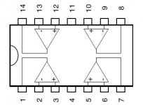
Here are the measurements for pins TL 494 (U7)
All voltages in DC
1 5
2 7,5
3 0
4 0
5 5V sawtooth 40uS
6 3
7 0
8 12
9 15V square 75uS
10 12
11 12
12 12
13 5
14 5
15 1
16 0
What do you think about that?
Best regards
All voltages in DC
1 5
2 7,5
3 0
4 0
5 5V sawtooth 40uS
6 3
7 0
8 12
9 15V square 75uS
10 12
11 12
12 12
13 5
14 5
15 1
16 0
What do you think about that?
Best regards
Re-check pins 9 and 10. They should be the same.
Which one is correct?
Pin 9 and 10 checked again, yes they are the same 15V square🙂
Pin 2 ,measures 10V
When you turn down the psu for the amp and the protect led lights up, then pin 3 raises to 5V
I don´t know if you can use that information🙂
Kim
Although it's probably not important at this point but it's strange to have pins 9 and 10 swinging higher than the voltage on pins 8 and 11. Are you sure that's what you have?
Do you have audio reaching the driver board?
Do you have rail to rail oscillation on the output transistors?
Are there any parts missing from the board as of now?
The amp has low voltage protection so turning the voltage down would cause it to go into protect. It shouldn't go into protect until the voltage reaches ~8.3v.
Hello 🙂
i take this post because i also have a problem with this amp
I hava a pop noise when i power up the radio, i verify the ground and it's ok so i don't know what to do 😕
I have 0.708 VDC on the teminal speakers when the pop noise appear with the subwoofer is connected on the amplifier Sinus live and i have 0.433VDC at output when the speaker in not connected
is it normal ?
Thanks for your help 🙂
Assuming that you had the meter connected directly across the speaker terminals, that's not normal. Post the DC voltage on all 14 pins of U2. Place the black meter probe on the negative speaker terminal. Place the red meter probe on the points where you need to measure the voltage.
Hello Perry 🙂
Thanks for your help 🙂
I'll do what you say but do you think i can continu to use the amp whitout a risk to destroy my subwoofer 😕 or i must stop to use it ?
i change the ground and the problem is the same....
Thanks 🙂
Thanks for your help 🙂
I'll do what you say but do you think i can continu to use the amp whitout a risk to destroy my subwoofer 😕 or i must stop to use it ?
i change the ground and the problem is the same....
Thanks 🙂
Hello
Thanks perry 🙂
so i'll Post the DC voltage on all 14 pins of U2 this weekend because i have not time at this time 🙄
thanks 🙂
Thanks perry 🙂
so i'll Post the DC voltage on all 14 pins of U2 this weekend because i have not time at this time 🙄
thanks 🙂
Hello Perry
I have time now 🙂
Are you sure it's the U2 circuit i must test ?
because the U2 circuit is near the preamp? and the U7 circuit is near the power supply it's the TL494C
So i think it's the power supply that make the pop noise ???
I don't know so can you confirm me that please ? 🙂
This is photos to show you that:
Thanks
I have time now 🙂
Are you sure it's the U2 circuit i must test ?
because the U2 circuit is near the preamp? and the U7 circuit is near the power supply it's the TL494C
So i think it's the power supply that make the pop noise ???
I don't know so can you confirm me that please ? 🙂
This is photos to show you that:
An externally hosted image should be here but it was not working when we last tested it.
An externally hosted image should be here but it was not working when we last tested it.
Thanks
The pop is almost certainly from the audio section if the amp produces clean audio after the pop.
What I was concerned about was the 0.7v of offset. U2 is in the feedback loop and that should determine the amount of DC offset.
What I was concerned about was the 0.7v of offset. U2 is in the feedback loop and that should determine the amount of DC offset.
Thanks Perry
so i'll mesure all
but have you got the service manual of this amp please ?
because i don't know where is the pin 1, 2, 3 etc....because i need that to post my measurements
Thanks 🙂
so i'll mesure all
but have you got the service manual of this amp please ?
because i don't know where is the pin 1, 2, 3 etc....because i need that to post my measurements
Thanks 🙂
Thanks a lot Perry
As you say previously, i put the black wire of my multimeter on the negative output speaker and the red wire of my multimeter on all pins of the circuit.
I have theses. is it normal ? thanks a lot Perry 🙂
Pin 1: 0V
pin 2: 0V
Pin 3: 0V
pin 4: 12.8V
Pin 5: 0V
pin 6: 0V
Pin 7: 32.3mV
pin 8: 0V
Pin 9: 0V
pin 10: 0V
pin 11: -12.9V
pin 12: 0V
pin 13: 0V
pin 14: 0V
Hello Perry 🙂
I found the service manual of this amp on the website of Luka but it seems it's not the same version 😕
but for the measurements i have made, it's seems to be normal for the Pin 4 and 11 but i don't now why i have 32.3mV on pin 7 😕 maybe it's my multimeter who isn't accurate...
and on the U2 circuit i have a red wire who doesn't apear on the service manual.
the red wire is on pins 14 and go to a cms resitor
this is 2 photos, do you think it's normal ? Thanks 🙂
An externally hosted image should be here but it was not working when we last tested it.
An externally hosted image should be here but it was not working when we last tested it.
It would appear that the meter is accurate enough if it can read 32.3mv. Did the ones that have 0v read 0.000v?
If so, are you sure you were making good contact with the pin? Sometimes a thin layer of oxidation can prevent making a good connection.
If so, are you sure you were making good contact with the pin? Sometimes a thin layer of oxidation can prevent making a good connection.
Supa Perry you are here 🙂 thanks a lot because i wait for your answer 😱😱 🙂
i'll re test with my multimeter but i'ts verry diffult to test without touching other pins because it's a really small circuit....
i test it now and i post the result 🙂
i'll re test with my multimeter but i'ts verry diffult to test without touching other pins because it's a really small circuit....
i test it now and i post the result 🙂
before re-test the u2 circuit i put my multimeter on the output terminal speaker and now i have 2.34VDC 😕 without a speaker before it's was 0.7V it is really strange 😕 and i have -0.19Vdc in continuous
- Status
- Not open for further replies.
- Home
- General Interest
- Car Audio
- SinusLive SL-A1500 help needed.