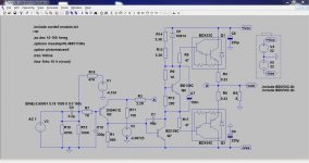
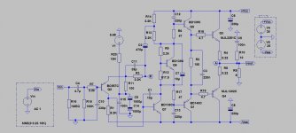
Hello.I had some spare parts and there has been some time since i last built a diy amplifier so i designed this small amplifier with singleton input stage and darlington output. I will be gratefull to read your comments...Supply rails will be about +-20V. D1 diode is a BAV21 and not OA91.
I read here in the forum that this diode helps with bootstrap rail sticking..
I read here in the forum that this diode helps with bootstrap rail sticking..
Attachments
Last edited:
Its a classic configuration and looks essentially fine 🙂
Thoughts... the DC offset looks like it will wander without some form of temperature compensation (and that's easier said than done), or without the use of a servo.
Personally, I'm not a fan of power darlingtons. Have you considered FET's or even Lateral Fet's ? That could make a really nice amp. Zobel network on the output maybe.
Thoughts... the DC offset looks like it will wander without some form of temperature compensation (and that's easier said than done), or without the use of a servo.
I think that the DC offset has to do with the changes of Vbe junction of input transistor Q2 due to temperature change.However i dont know what the dc offset range will be.So the best solution is what you suggest,a DC servo.
For the time being i will try these darlingtons because i want to get rid of some parts sitting in my box...I will try it in simulation though.Have you considered FET's or even Lateral Fet's ?
I made a small pcb layout 5x6 cm which includes zobel network. this pcb is just at the beggining and not tested for errors..
Here are the LTSpice files if anyone is interested.First decompress the zip file so you are able to use the darlington spice models.
Attachments
Last edited:
Nice amplifier that should work.
You have done a good job.
I'm starting to like the updated "classic" designs again. This circuit reminds me of the first transistor amp I "designed" and built in high school. I had successfully designed and built a great tube amp but I did not know how to get the results I wanted from transistors. The amp (more modest than this design for sure) did not initially work as I had intended (terrible in many ways) but by making adjustments and scaling resistors I made it work pretty good (although at the time I couldn't tell you why). In fact it still worked 35 years after I built it when I finally gutted it to use the enclosure for another project.
Since I had the single ended transformer (not very useful nowadays 😉 ) and boxes of salvage parts, I breadboarded up a headphone amp similar to "Death of Zen" with a CCS biased output transistor. This is a departure from my usual tinkering. To say I was impressed is an understatement.
With modern transistors and premium parts available, this topography deserves a second look.
I've got your file although it needs a bit of work to run the simulations.
I'll perhaps have a play later 🙂
I'll perhaps have a play later 🙂
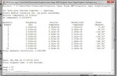
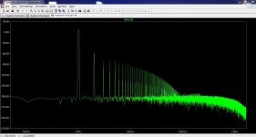
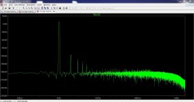
i like the difference between 2nd and the rest of harmonics.. some tuning maybe needed maybe it is overcompensated,maybe the quiscent current is low.
Bu the way i studied most posts of your thread http://www.diyaudio.com/forums/solid-state/119151-my-mosfet-amplifier-designed-music.html
Bu the way i studied most posts of your thread http://www.diyaudio.com/forums/solid-state/119151-my-mosfet-amplifier-designed-music.html
Last edited:
Yes, the 2nd harmonic predominates. I've no doubt it could be tweaked but just how far is hard to say.
(I'm currently working on an updated version of that lateral FET amp, still with the same single ended topology)
(I'm currently working on an updated version of that lateral FET amp, still with the same single ended topology)

is this distorion audible???? 😀
if only we could leave 2nd harmonic be present and eliminate all the others..
if only we could leave 2nd harmonic be present and eliminate all the others..
You would have to say "not audible" but then again the same can be said for the "blameless Class B" type circuit and yet when you compare the two audibly... well, somethings going on 😀
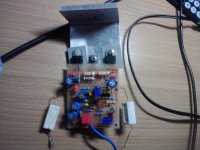
Hello! I built the amp and it worked fine.There was a mistake on the pcb regarding pin layout of BD139 transistors which i noticed after i etched the boards but i overcame it. The amp sounded really nice the poor darlingtons used in the output stage,with strong bass and very clean vocals. I think it is due to dominant 2nd harmonic content.
I decided to move on to a new design based on EF TYPE II Output stage.
I attach the LTSpice file of the new amp.
Any suggestions appreciated!!
I decided to move on to a new design based on EF TYPE II Output stage.
I attach the LTSpice file of the new amp.
Any suggestions appreciated!!
Attachments
Interesting little amp - nice work!
I also just finished the paper design on a small 12 W class A amp singleton input. I will build it and post it up in the few weeks.
I also just finished the paper design on a small 12 W class A amp singleton input. I will build it and post it up in the few weeks.
Member
Joined 2009
Paid Member
The amp sounded really nice
I decided to move on to a new design based on EF TYPE II Output stage.
If it sounded really nice, why change to a new design ?
If it sounded really nice, why change to a new design ?
In the first design i used BDX53C-54C darlington type transistors which are not linear,have low Ft and dont have an adequate Safe operation area to be used with +-35V power supply and output power of 50-60watt rms / 8ohm.
I'm sure it does sound good I see you changed the input stage biasing around.
Yes i changed it after reading bob cordell's and douglas self's books about dc servos which state that this is a better point for the servo,whether it is a trimpot or an opamp.
i am planning to use 2SC5200/1943 for output and 2SC4793/1837 for drivers as i already have them.
Here are some photos of the initial design
Attachments
![P270112_01.21_[01].jpg](/community/data/attachments/335/335846-6b01dbf076e26d7ad82716f5ec7acd08.jpg?hash=awHb8HbibX)
Last edited:
Got it to run 🙂
Thanks for explaining the biasing, yes it makes sense to apply any correction to a point where "no signal" is present.
Thanks for explaining the biasing, yes it makes sense to apply any correction to a point where "no signal" is present.
Just trying your spice file I'm getting -32 volts DC on the output... think I can see why.
change the dc value of V1 source to 2.82467
- Status
- Not open for further replies.
- Home
- Amplifiers
- Solid State
- Singleton Input Stage Amplifier