With sound travelling at about 340 m/S in room-temperature air, the wavelength of a 50 Hz acoustic wave is 6.8 metres (over 22 feet).
If the port is less than, say, one quarter of this distance from the woofer, then any time delay from it becomes irrelevant.
In other words, you only need to worry if your port openings are at least 2 metres / 6 feet away from the woofer. This is incredibly unlikely to happen.
I understand the principle, but I'm pretty sure the rule of drivers placing drivers within 1/4 the wavelength of the crossover frequency is not the whole story.
Using your example of 50hz, that gives me 4 drivers that are within 1/4" wavelength of each other. They should all respond the same? But the graph I attached above demonstrates that when played individually, they do not measure the same. They are not hugely different at 50hz, but they are not the same.
Here is an interesting anecdote from Geddes. He was asked about getting "room gain" by placing a sub in a corner or by a wall, and his answer is that room gain does not exist. Instead, he said you excite different room modes by placing a sub against a wall or in a corner. And he said a sub in a corner excites more room modes, but total energy is the same.
We all know that room modes exist, and they are dependent on the location of the speaker and the listening position. Multiple subwoofer theory leverages this principle, using the interaction of the different room modes from different subwoofers to control each other. And I'm demonstrating that drivers that are close together can be used to the same effect. I don't know about you guys, but I find that fascinating. I mean, most people would say it can't work...but I sort of disagree.
If your data is good, it shows that there is a difference between driving one woofer, and driving several. But we don't know that the difference is caused by path length differences, do we?Using your example of 50hz, that gives me 4 drivers that are within 1/4" wavelength of each other. They should all respond the same? But the graph I attached above demonstrates that when played individually, they do not measure the same. They are not hugely different at 50hz, but they are not the same.
I suspect the reason is something else - not path length differences, but something else.
A preamble: the reason why our loudspeakers are so terribly inefficient, is because it's hard to couple energy from a small vibrating diaphragm (speaker cone) into this very low-density medium.
When you put two identical woofers side by side, and drive each of them with the same power as before, it seems reasonable to expect a 3 dB increase in SPL. (Double the power in, double the acoustic power out.)
Some years ago, diyAudio member Printer2 did this measurement - and he found that he got 6 dB more SPL, not 3 dB! This was repeatable, not a fluke.
When the speaker cone diameter is much less than the wavelength of the emitted sound, coupling to the air is poor. The strength of the coupling is proportional to the ratio of wavelength/(speaker diameter). At any one frequency in this range, doubling the speaker cone area would double the efficiency of the coupling from mechanical motion to actual acoustic energy in the sound wave.
I think the reason Printer2 saw a 6 dB increase in SPL is because of this. Doubling the effective cone area (two woofers) also doubled the coupling efficiency to the air. So now you had twice as much electrical power (+3dB), but also twice the efficiency at putting that electrical power into the air (another +3dB). Net result: a +6dB gain.
I wonder if this effect is what you're seeing with those woofer measurements.
Room modes are an entire can of worms on their own. I don't know enough about that to say anything useful. 🙂
-Gnobuddy

I'm not sure about the 2 drivers next to each other. With 2 woofers playing the same signal and acting as the same woofer, possibly you need to include the area inbetween the two drivers when calculating SPL?If your data is good, it shows that there is a difference between driving one woofer, and driving several. But we don't know that the difference is caused by path length differences, do we?
I suspect the reason is something else - not path length differences, but something else.
A preamble: the reason why our loudspeakers are so terribly inefficient, is because it's hard to couple energy from a small vibrating diaphragm (speaker cone) into this very low-density medium.
When you put two identical woofers side by side, and drive each of them with the same power as before, it seems reasonable to expect a 3 dB increase in SPL. (Double the power in, double the acoustic power out.)
Some years ago, diyAudio member Printer2 did this measurement - and he found that he got 6 dB more SPL, not 3 dB! This was repeatable, not a fluke.
When the speaker cone diameter is much less than the wavelength of the emitted sound, coupling to the air is poor. The strength of the coupling is proportional to the ratio of wavelength/(speaker diameter). At any one frequency in this range, doubling the speaker cone area would double the efficiency of the coupling from mechanical motion to actual acoustic energy in the sound wave.
I think the reason Printer2 saw a 6 dB increase in SPL is because of this. Doubling the effective cone area (two woofers) also doubled the coupling efficiency to the air. So now you had twice as much electrical power (+3dB), but also twice the efficiency at putting that electrical power into the air (another +3dB). Net result: a +6dB gain.
I wonder if this effect is what you're seeing with those woofer measurements.
Room modes are an entire can of worms on their own. I don't know enough about that to say anything useful. 🙂
-Gnobuddy
I spent some time investigating coaxial speakers while preparing for my current build, and I'm noticing that it doesn't seem to matter if there isn't any radiation from the center of the coax speaker. For example, my B&C drivers have a wave guide that covers the majority of the speaker cone. There are other coaxials that are even more pronounced. And Genelec "the ones" have "concealed" drivers in a MTM configuration...they radiate out the top and bottom, and a little to the sides, which I believe creates the directivity (i.e. beaming) characteristics of a driver that is larger than the genelec speaker.
The wave formed by the two drivers forms as though it is coming from a much larger driver, so maybe you have to calculate the size of the "virtual" driver?
But I don't know. Just speculating!
But for my design, I think phase and proximity to boundaries are the critical elements.
Phase is probably the biggest reason. Because the drivers are offset and radiating in different directions, they will never be 100% in phase. In pro audio they use this configuration to achieve bass directivity. If both drivers are in phase, they create cancel each other, creating forward and rear cones of sound, which isn't very useful. But in pro audion they will delay the front woofer so the front woofer is aligned with the rear output going forward. But at the same time the output of the front woofer that would radiate behind the speaker is cancelled by the rear woofer. Another option is to delay and invert the rear sub, which creates better cancellation, but can negatively affect sound quality from what I've found.
I was originally lead to pursue bass directivity as the principle that this speaker design would work under. (That's why I was looking at coaxials and beaming effects of coaxials, MTMs, etc.) Atleast in my room, configuring the speakers for directivity does not achieve significantly better low frequency response over a traditional speaker.
So I forgot about directivity and have worked on making adjustments that directly affect measurements. And adjusting delays is the thing that seems to work the best!
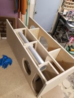
I built the new cabinet. The port design seems to work quite well! It has good output at 20hz, no issues with the 90 degree turn at the bottom of the ports. And my measurements say the distortion I was seeing at 20-30hz is practically gone! Before it was as much as 10%. It was 2.5% @80dB, and I bet most of that is the first cabinet I built with a slot port.
I'm happy with performance, but not sure about size. It's quite big. 18"x18"x48". It'll look smaller with 2" radius corners, but I don't know if that's enough. I am considering making it narrower, reducing the subwoofer portion and tuning a bit higher. I could reduce the subwoofer by 20% and still have an F3 of 22hz...

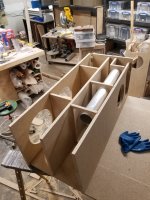
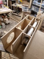
Below are a few pictures showing the internal construction. Keep in mind this is still a prototype. I'll do a proper build thread when I make a finished version.


I'm happy with performance, but not sure about size. It's quite big. 18"x18"x48". It'll look smaller with 2" radius corners, but I don't know if that's enough. I am considering making it narrower, reducing the subwoofer portion and tuning a bit higher. I could reduce the subwoofer by 20% and still have an F3 of 22hz...
Below are a few pictures showing the internal construction. Keep in mind this is still a prototype. I'll do a proper build thread when I make a finished version.
Attachments
I think this is purely a geometric effect. Imagine a thin concentric ring drawn on the speaker cone. It's area is (ring width)x 2 x Pi x radius....I'm noticing that it doesn't seem to matter if there isn't any radiation from the center of the coax speaker.
The relevant bit is that the area of the ring is proportional to its radius.
This means a ring with a 4" radius (at the outer edge of an 8" driver) has four times as much radiating area as a same-width ring with only 1" radius, near the centre of the cone.
No wonder most of the acoustic radiation comes from the outer portions of the cone!
The same geometric effect also applies to aircraft propellers. You can have a huge "spinner" (bullet shaped hub) in the middle of the propeller, because that portion of a propeller contributes very little to propeller thrust.
-Gnobuddy
That effect is used in radio astronomy, where a few dishes spaced far apart can behave like a single, much-larger dish.The wave formed by the two drivers forms as though it is coming from a much larger driver, so maybe you have to calculate the size of the "virtual" driver?
This doesn't increase the actual light collecting area as much as a single enormous (but quite impractical) dish would have. But it can sharpen the directivity of the array (it can look at smaller areas of sky, and resolve smaller objects).
The same math is also used, in a simpler fashion in long line-array loudspeaker systems. The math is simpler because a line array is one-dimensional, rather than two-dimensional disc radiators. It's basically exactly the same mathematics that describes an optical diffraction grating, which used to be standard stuff in classical optics college physics courses.
The math is simple for two woofers spaced very far apart (two point sources, in effect).
It's also simple for two woofers placed very close to each other (much less than one acoustic wavelength), which act like one source with the combined radiating area of both cones.
In between those two limits, the math is much more complicated.
For our purposes, given long bass wavelengths, I don't think that small distances between woofers or subwoofers matters.
-Gnobuddy
If all the drivers were on the same plane and playing in phase, then you would be correct. But you are applying a generic rule of thumb to a situation where it does not apply.Ror our purposes, given long bass wavelengths, I don't think that small distances between woofers or subwoofers matters.
-Gnobuddy
There are a lot of thought experiments you could do to understand the different ways this rule of thumb falls apart. Think about line arrays. There is a thing called "beam forming" using delays. It is similar to bass directivity, but more controlled.
Then there is bass directivity. It is pretty simple, well established, and it features multiple low frequency drivers in close proximity, which do not act as a single driver.
And even with the well understood multiple subwoofer method of correcting low frequency response in a room, there is no rule saying that subwoofers have to be a minimum distance apart. In fact, Geddes says he doesn't care where your subwoofers are. He says corners are good because they excite more room modes, but he said flat out that it doesn't matter where they are.
I know this is 'outside the box', but I think the box is at fault! I think the constrains that define the limits of the standard box need to be re-drawn!
I am seeing a lot of chatter about how low frequency response of a ported enclosure drops off at low volumes, with people saying the larger the port is, the more low frequency response you lose at low levels.
I am assuming a comparison between two subwoofer cabinets that have been modeled and design correctly, with the port length increasing as the port area increases, and the box volume increasing to compensate for the volume the larger port displaces.
So if we are comparing correctly designed subs with the same tuning and the same driver, can we generalize anything about the effect of port area on low frequency output at low listening levels?
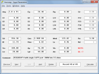
The specifics of my design is 100L/ 3.5ft^3 box, tuned to 21hz, with either a single 3.875" port, or two 3.875"ports. Driver is RSS265HF-4 10" sub. The max port velocity with the single port is simulated to be 32m/s
For the example you give, assuming no losses and linear operation, the low frequency extension will remain effectively the same if the port area and port tube length are doubled, and the volume of the chamber is kept at 100 litres, regardless of the input level.
Attachments

And he said a sub in a corner excites more room modes, but total energy is the same.
The low-frequency acoustical loading on the driver diaphragm will be increased if the loudspeaker is placed in a corner, and therefore more of the electrical input power will be converted into sound energy.
Thanks. I did notice a shallow downward slope from 40hz to 20hz with the single port design, when measuring at 100dB. My port is not flared on either end, so there must be some losses from friction and turbulance at the port openings.For the example you give, assuming no losses and linear operation, the low frequency extension will remain effectively the same if the port area and port tube length are doubled, and the volume of the chamber is kept at 100 litres, regardless of the input level.
The 2 port design does seem to perform much better in that regard.
The only issue I have with the new design is there is some audible air flow noises when playing a low frequency tone. It isn't bad, but it exists. I once had a Genelec 7060B sub, and it made zero noise....so for the last 2 days I have been thinking about how I can improve that aspect. I thought about going back to a slot port, since my test cabinet with a slot port is pretty quiet (currently the left speaker!). But I also have been thinking about molding a custom flare/ transition for the 2 ports design which will likely fix the noise.
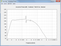
By way of update, I have some data. These measurements were taken from near the port. There is a slight issue around ~100hz. I think this might be caused by the way the ports exit into a recessed chamber? I think it could be solved by making a molded/ contoured exit for the ports.
But to meet my design goals, I need to shrink the entire speaker. So I am working on another solution. However, this port configuration does seem to be a viable option given the right speaker cabinet.
The EQ applied is primarily the high and low pass filters. And I think the bump at ~23hz is because the microphone was closer to the port than the driver.
- Home
- Loudspeakers
- Subwoofers
- Single Port vs 2 Ports; Affect of Port Area on Low Level Output?