Hi Hugh:
>I stand corrected.<
No problem.
>I lean towards the single diff.<
You mean a single non-complementary input differential pair, with the second-stage being?
The terminology used in this thread has stayed arbitrary for so long that I would like to confirm where everyone stands and what everyone means. 🙂
For instance, I can state that I have previously used what I call a dual differential circuit in a commercial product, but I should clarify that this was _not_ a complementary differential circuit.
regards, jonathan carr
Jonathon,
yes, precisely that, with ....a single ended voltage amplifier, some supplied from bootstrap, and some from a constant current source.
It is always tricky to use words to describe a topology. Different folks, different strokes.....
But nice pictures take longer to put on the forum, dammit......
Hugh
Hi Hugh (again):
From your post:
http://www.diyaudio.com/forums/showthread.php?postid=266958#post266958
>One valid, real-world approach is to have extremely fast devices and very short, non-inductive feedback and signal paths which minimize group delay and thus bring down overshoot and distortion to vanishingly low levels.<
I completely agree (some of my previous posts cover the same territory), but will add that the above should be accompanied by a low-pass input filter so that the circuit does not need to deal with HF signals that may possibly give it trouble.
IMHO, unless the designer is willing to implement the aforementioned attention to detail in the actual design (including the physical construction aspects), this thread discussion of what topology is best is a somewhat academic exercise.
regards, jonathan carr
Even though it LOOKS symmetrical, I think npn and pnp are not exact opposite in behavior. So if the behavior is not an exact opposite, would it be that the output like "have a shadow" or "blurry"?
Completely correct. A complementary design reduces even order distortion, not canceling it out. But again, the main mechanism of distortion is the output stage, if this stage produces even order distortion (and it will, because NPN and PNP are not completely complementary) we'll get overall even order distortion, regardless of a complementary input diff stage or not.
The complementary input stage has more sensitivity to the bias influence of VAS than a single LTP with a current source. A big disadvantage. To come out of this problem you need emitter degeneration of the VAS stage. On the other side a complementary design has lower distortion levels as john curl has pointed it out. So we've one advantage and one disadvantage and the freedom to design both topologies right...
BTW complementary designs have only slightly more components (about 10% or so) than asymmetrial designs.
>This may help.
Thanks ! I don't know if it's relevent or not, but something I've noticed is that A seems to have better recovery characteristics than C............. I.E. coming out of clipping there is not as much 'lag' or something (the little step off of the flat place going back down to the wave shape) .......... mike
Thanks ! I don't know if it's relevent or not, but something I've noticed is that A seems to have better recovery characteristics than C............. I.E. coming out of clipping there is not as much 'lag' or something (the little step off of the flat place going back down to the wave shape) .......... mike
mcp:
Thanks for the figure. Most convenient.
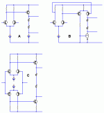
A Japanese EE would call A "Single Differential", B "Dual Differential", and C "Complementary Differential". Don't know about elsewhere.
regards, jonathan carr
Thanks for the figure. Most convenient.
A Japanese EE would call A "Single Differential", B "Dual Differential", and C "Complementary Differential". Don't know about elsewhere.
regards, jonathan carr
There's quite a few more, so I suggest you with stick with
pictures describing diff pairs after the first two.
pictures describing diff pairs after the first two.
>A Japanese EE would call A "Single Differential", B "Dual Differential", and C "Complementary Differential". Don't know about elsewhere.
Makes sense. I tend to call A single and C dual, but your nomenclature is much more succint .......... mike
Makes sense. I tend to call A single and C dual, but your nomenclature is much more succint .......... mike
Yes, thanks, MCP.
If we actually keep talking about different diff-input stages, someone should probably paste that chart every few pages, so we all know what hook-up is being discussed.
jcarr> A Japanese EE would call A "Single Differential", B "Dual Differential", and C "Complementary Differential"...
MCP's image with Jcarr's "Japanese EE" terminology, tight layout:
I have a copy on my machine but the URL is ugly. Wrap the UBB URL tags around this tiny-URL: http://tinyurl.com/vuqt
If we actually keep talking about different diff-input stages, someone should probably paste that chart every few pages, so we all know what hook-up is being discussed.
jcarr> A Japanese EE would call A "Single Differential", B "Dual Differential", and C "Complementary Differential"...
MCP's image with Jcarr's "Japanese EE" terminology, tight layout:
An externally hosted image should be here but it was not working when we last tested it.
I have a copy on my machine but the URL is ugly. Wrap the UBB URL tags around this tiny-URL: http://tinyurl.com/vuqt
Most of the previous comments discuss complementary differential, but don't actually show its true advantages.
The MAIN advantage of comp-diff input is that the SECOND STAGE is symmetrically driven. This reduces the effort of just one device having to drive the output stage, and effectively doubles the available class A current. It also gives a doubling in the open loop gain, without decreasing the phase margin, and third, with bipolar transistors, it can cancel the input bias, so that an input coupling cap is unnecessary. This offsets the extra parts count.
There are other advantages, especially with FET input designs, but this should be enough for this discussion.
AKSA said:
Pavel, have you tried the prosaic double emitter follower output stage, particularly Self's Type II, in side by side listening comparisons, against your CFP? I have done tests with others some years back and concluded strongly in favor of the double emitter follower.
You make some challenging comments about RF injection into the amp too, which I'm looking into. Great work, Pavel!
Cheers,
Hugh
Hugh,
A colleague of mine built very similar output stage with double emitter follower output. He used smaller transistors in parallel (I think they were BD243), these were considerably less linear [Ic=f(Ib)] compared to 2SA1943/2SC5200. The listenings tests were made and CFP version was preferred (the circuit shown on my www). CFP version also did measure better than 2SE.
Thanks for your interests in RF intermodulation influence (residual spikes of D/A conversion), this really gives enormous sonic improvement to filter the spikes properly and effectively.
Pavel
Alternatively, complementary differential has several limitations. As was pointed by NP the quiescent current in the VAS after complementary differential input stage has poor stability. For the reason of stability, differential pairs load are resistors, thus the VAS input nodes have low impedance. The ordinary Miller compensation will be ineffective, as the dominant pole is formed by the VAS output network. Without Miller compensation the VAS output impedance would be high so the nonlinear input current of the output stage might contribute to overall distortions. Extra precautions should be taken e.g. extra emitter follower after VAS.
Neither do I 😕
Are you referring to the "current mirrors as the input diff stage load" item that was talked about a short time ago in the discussion on Sloan's designs ?
mlloyd1
Are you referring to the "current mirrors as the input diff stage load" item that was talked about a short time ago in the discussion on Sloan's designs ?
mlloyd1
john curl said:I don't know what you are talking about, Dimitri.
Pavel,
Interesting; thanks for the response.
I know the linearity of the drivers and output devices is very important to sonics, as is Vbe and beta matching of like devices where output pairs are used.
I did the side by side comparison with 2SC5200/2SA1943 on both; one, a CFP (with 100R base emitter resistor on the outputs) and the other a DEF Type II with 150R/100nF between driver emitters.
There really was no comparison, with DEF being superior, particularly in engagement, whatever the hell that means.......
Your work on low pass input filters is confirmed by Jonathan, in fact. That's good enough for me. No doubt; unless the amp is intrinsically band limited elsewhere, and probably despite that, we should use them liberally!
Do you chime them in at say 3dB down at 50KHz?
However, polystyrene or mica - that is the question!
Cheers,
Hugh
Hi,
Both approaches suggested LP filters in the GNFB loop as I understood it. But, wouldn't it be much easier on the amp to implement the filter right at the input?
That would be a nice starting point. Personally I like it more higher and use the Miller capacitance effect to do the work for me...
Valves are easy for that, especially high µ triodes.
To my ears, silvermica caps. They're as close to the ideal cap one can get and sound great.
Cheers,😉
No doubt; unless the amp is intrinsically band limited elsewhere, and probably despite that, we should use them liberally!
Both approaches suggested LP filters in the GNFB loop as I understood it. But, wouldn't it be much easier on the amp to implement the filter right at the input?
Do you chime them in at say 3dB down at 50KHz?
That would be a nice starting point. Personally I like it more higher and use the Miller capacitance effect to do the work for me...
Valves are easy for that, especially high µ triodes.
However, polystyrene or mica - that is the question!
To my ears, silvermica caps. They're as close to the ideal cap one can get and sound great.
Cheers,😉
JC wrote: I don't know what you are talking about, Dimitri.
Self singled out several types of distortion:
Input stage nonlinear transfer characteristic
Input stage CMRR
Voltage Amplifier Stage nonlinear transfer characteristic
Non-linear VAS loading
Output stage large-signal nonlinearity
Output stage crossover
Output stage switch off
From the above, Complementary Differential has two times higher gain, it has even distortion compensation in VAS, probably the JFET input will have better CMRR.
I’m speaking about nonlinear VAS loading. In Single Differential design the almost universally adopted Miller compensation effectively lowers VAS output impedance. Thus DEF with that nonlinear input resistance works well.
In Complementary Differential VAS feeds from much lower collector resistor, and the loop gain inside Miller loop would be lower. IMXO Miller compensation isn’t effective, 1 just eats the bandwidth, 2 is the best. Also one can isolate output stage from VAS by TEF instead of DEF.
Attachments
- Status
- Not open for further replies.
- Home
- Amplifiers
- Solid State
- Single or dual differential?