Silence is golden
And my wish is let us follow the topic (that words in black bold in the upper part of the screen, just below diyaudio.com) 🙂
I understand that you all have that much to type here, but please don’t allow Nonsense Expands To Fill The Bandwidth Allotted To It
And my wish is let us follow the topic (that words in black bold in the upper part of the screen, just below diyaudio.com) 🙂
I understand that you all have that much to type here, but please don’t allow Nonsense Expands To Fill The Bandwidth Allotted To It
hitsware said:I=V/Z is a linear relationship BUT
the Z of a driver (or any reactance)
is (by definition) not. Something to
do with 'rate of change'
So what if the Z isn't linear versus frequency? That's not what the author said. What the author said was that current and voltage will only have a linear relationship if the circuit is purely resistive.
Here, read it again:
By Ohm's law, the current in a speaker voice coil is the amplifier output voltage divided by the speaker impedance. Therefore, the current can only be linearly related to the voltage if the speaker presents a purely resistive load to the amplifier.
I'm sorry, but Ohm's Law is a linear equation whether you're using resistance or reactance or impedance and therefore there will be a linear relationship between current and voltage even in a reactive circuit.
I = V/R, V = I x R, R = E/I
I = V/X, V = I x X, X = V/I
I = V/Z, V = I x Z, Z = V/I
se
fdegrove said:Seems to me some people have difficulty in differentiating DC from AC behaviour...
Back to the kindergarten and Thevenin for some of us I reckon??
Eh? Since when does Ohm's Law become non-linear under AC conditions? The relationship between current and voltage is linear whether DC or AC.
Here's your kindergarten lesson for today:
Ohm's Law for resistance:
I = E/R, E = I x R, R = E/I
Ohm's Law for reactance:
I = E/X, E = I x X, X = E/I
Ohm's Law for impedance:
I = E/Z, E = I x Z, Z = E/I
Since all of these equations are linear, how does voltage somehow come to have a non-linear relationship to current under AC conditions?
se
Lets start another thread about it and I'll respond best I can.
My fault this one digressed enough to make the tone of some of the responses get sort of aggressive.
(or I may be flattering myself 🙂 )
This forum (new to me ) is a little differant than the FR forum in that more digression is wellcomed over there.
I'd like to see this thread explore active differential
(NOT .....
Counting xfmrs .....
Simply to make it comfortable and stimulating for guru types.
(which i think you and i can agree on ..... we ain't no JC, or NP
or even fred))
front ends to the max.
Off to Raleys ........... mike
hitsware said:Lets start another thread about it and I'll respond best I can.
Here you go:
http://www.diyaudio.com/forums/showthread.php?s=&threadid=22915
se
 ) ....
Maybe this is not about the main topic. But since there are many expert here, I would like to ask another question.
Once I read an article by Japanese about current power amp. He said that what drives a speaker really is current, not voltage.
But all this time we define audio power amp as a device to amplify voltage. That is like there is sinusoidal 1Vpp input, the power amp is amplifying the voltage to certain value, like 30Vpp.
If the speaker is purely resistive, we can get clean sinusoidal current from sinusoidal voltage, since the load is pure resistive. But since the speaker is Impedance (zr+zl+zc), not pure resistive, the current shape certainly be different from the voltage shape, cause of Zspeaker depends on frequency.
The idea is this. What happens if we make an audio power amp, that sense voltage shape input (like sinusoidal), but gives output of current, with that particular input shape.
Is this what we know as "current feedback" (usually using opamp like the ssm- Analog Device current feedback power amp), or is it something else?
lumanauw said:Maybe this is not about the main topic. But since there are many expert here, I would like to ask another question.
Once I read an article by Japanese about current power amp. He said that what drives a speaker really is current, not voltage.
Yes, ultimately it's the current flowing through the loudspeaker's voice coil which produces the time-varying magnetic field which interacts with the fixed magnetic field in the gap and causes the cone to move.
But all this time we define audio power amp as a device to amplify voltage. That is like there is sinusoidal 1Vpp input, the power amp is amplifying the voltage to certain value, like 30Vpp.
Yes. That's because pretty much all loudspeakers are designed to be driven by a voltage source rather than a current source.
If the speaker is purely resistive, we can get clean sinusoidal current from sinusoidal voltage, since the load is pure resistive. But since the speaker is Impedance (zr+zl+zc), not pure resistive, the current shape certainly be different from the voltage shape, cause of Zspeaker depends on frequency.
No, if you feed a sinusoid into a reactive circuit you'll get a sinusoid output.
The idea is this. What happens if we make an audio power amp, that sense voltage shape input (like sinusoidal), but gives output of current, with that particular input shape.
You'll get a sinusoid either way.
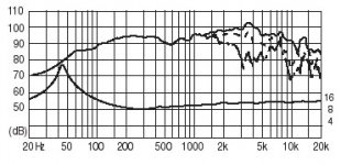
The problem is that you'll get a frequency response that resembles the speaker's impedance curve.
For example, the image I've attached is of the frequency response and impedance plot of a Fostext FE208E Sigma full range driver.
The plot along the top is the driver's frequency response as driven from a voltage source amplifier and the plot below is its impedance versus frequency.
If you drove the driver from a current source, its response would resemble its impedance plot, and instead of the gradual rolloff of its low frequency response, you'd get a big peak in its low frequency response.
se
Attachments
What will it sound?
My idea of current amp is like this. I'll take an example from schematic in post no.81 (by hitsware). Let's assume that this is a working amp (not experimental).
The output is taken from the drain junction of SK and SJ. Push-pull amp will have this kind of output, usually taken in the junction of 0.22ohm/5W resistor (after emitors, if it is EF)
To get current sensor, before going to loud speaker, between the junction of those drains before output to sepaker, we put R, like 1ohm, to detect what is the current delivered to the speaker.
Then, this current figure is compared to the voltage signal in the differential input.
This way we don't need the 10k and 510ohm voltage feedback divider, since we are detecting the output current in the 1ohm resistor drop. That is the data for the differential to measure the difference in signal input and current output. Maybe this is "voltage input - current output" audio power amp. But is this possible? What will it sound?
This idea is coming from the statement of japanese I mentioned before that speakers are driven by current, not voltage.
Dear lumanauw,
this topic name: single or dual differential
here is something about current drive
http://www.diyaudio.com/forums/showthread.php?s=&threadid=22430
http://www.diyaudio.com/forums/showthread.php?s=&threadid=22107
this topic name: single or dual differential
here is something about current drive
http://www.diyaudio.com/forums/showthread.php?s=&threadid=22430
http://www.diyaudio.com/forums/showthread.php?s=&threadid=22107
Dimitri, it would seem that this current drive question does belong on a separate thread.
For the record, current drive is not unusual for motor drive applications, and has been used for many decades. However, loudspeakers, under some circumstances, could benefit from current drive, BUT NOT typical speaker systems.
Also, I could care less whether SE is on this website or not. I like this website, because it is fast moving, and many inputs post interesting schematics and other references. I would prefer to keep on subject, if possible, but I'm sure I also have diverted from the original subject on many occasions, over the years. We were having an interesting discourse on differential input stages, but now this is pretty much lost in the noise of other inputs.
>I would prefer to keep on subject, if possible,
ref😛ost 199
If I understand Hugh right, the single pair configuration has more even harmonics not from the pair itself, but from the single ended (as a rule) next stage. Correct? Isn't the pair itself push pull by definition? .............. mike
ref😛ost 199
If I understand Hugh right, the single pair configuration has more even harmonics not from the pair itself, but from the single ended (as a rule) next stage. Correct? Isn't the pair itself push pull by definition? .............. mike
Sorry, my mistake. I will get back into track.
Like one post said, is it true dual differential gives less harmonics, because they cancel each other? What is really the benefit of having less harmonics? Isn't that tubes have warm sound because they have big harmonics?
About the current drive power amp, I make it a new thread, because it is about very different topic in http://www.diyaudio.com/forums/showthread.php?s=&threadid=22959
Hi,
No, differential would give less distortion with less even harmonics due to distortion cancelation.
Tubes can be made to sound icecold just the same.
The idea of tubes having a warmer ( richer?) sound is just plain BS.
Cheers,😉
Like one post said, is it true dual differential gives less harmonics, because they cancel each other? What is really the benefit of having less harmonics? Isn't that tubes have warm sound because they have big harmonics?
No, differential would give less distortion with less even harmonics due to distortion cancelation.
Tubes can be made to sound icecold just the same.
The idea of tubes having a warmer ( richer?) sound is just plain BS.
Cheers,😉
to hitsware
Jc wrote: The complementary differential has lower distortion, all else being equal.
This is absolutely right. The differential pair alone is symmetrical, but when the signal is passed on to the VAS stage, it loose symmetry in current mirror, or in resistive load, or simply the VAS stage transfer function is not symmetrical.
>Tubes can be made to sound icecold just the same.
Ya Mon ! I once had to modify a tube preamp to make it sound like a tube preamp.........mike
Ya Mon ! I once had to modify a tube preamp to make it sound like a tube preamp.........mike
Yes, true, the fully complementary input stage should give less distortion because of even order cancellation, particularly at the voltage amplifier, which is then fully complementary as well.
The single diff stage will not, however, have particularly low TOTAL distortion, other things being equal. Its configuration merely gives an inverting node at like potential - the base of the feedback transistor - so that like phase signal from the output can be injected as negative feedback.
Truth is, the diff pair as used in most SS amplifiers is dual input, one inv and the other non-inv, but single-ended output. This is an important distinction.
If it were used as a differential output then its even order distortion would be nulled. Lots of people would be happier....
No, as was suggested, the chief benefit of a dual diff pair input stage is that it permits use of a fully complementary voltage amplifier, which will null its own even order distortion, leaving only very low levels of odd order.
However, and here's the rub, do we want to reduce the even order distortion, while leaving the odd order essentially unaffected? Do we really want to skew the formation of harmonics towards low levels of odd-order, with even-order submerged below the noise floor?
I would suggest we don't. It just ain't musical. Another point which NP made, a bloody good point, is that a single diff stage leads to a single-ended voltage amplifier, which is almost always supplied with current from a current source supported from the rail. This arrangement facilitates marvellous offset control - no small feat.
The feedback node on a SS amplifier is required to undertake two tasks; AC voltage feedback, very important and quite obvious; and DC offset control, holding the speaker output at very close to zero volts. This task is vital; it's the amp equivalent of a regular heartbeat for a mammal. If the output deviates even a couple of volts from zero (and the nature of offset control failures are normally rail excursion catastrophes), then the speaker either overheats, or dies outright, and often takes the output stage with it too.
So, here are two very good arguments for a single differential input stage. Of course, I need not emphasize that this topology halves the component count, and is cheaper, simpler - less to go wrong! (that's the third argument!)
Cheers,
Hugh
A comment on terminology and how it is used by different people to mean different things:
At least in Japan, "dual differential" specifically means a topology in which an input differential pair feeds its output to another differential pair (in series). A topology with two input different pairs - one N and one P - is called (at least in Japan) "complementary differential".
I raise this issue because both of these terms are commonly used in catalogs and brochures published by the big Japanese electronic conglomerates (and other audio manufacturers), and unless you are clear as to who is using these terms and what what they mean by doing so, you may be left with a totally erroneous impression of what the circuit topology is.
Previously alluded to in this post.
http://www.diyaudio.com/forums/showthread.php?postid=258889#post258889
hth, jonathan carr
So, we've got 2 confincing answer about single differential from AKSA and Mr.Pass. Is there any designer from pro-audio that used to applicate dual differential? What is the main reason to use dual differential? Is it just for easiness, or symmetrical look? Even though it LOOKS symmetrical, I think npn and pnp are not exact opposite in behavior. So if the behavior is not an exact opposite, would it be that the output like "have a shadow" or "blurry"?
Thank you JCarr,
I stand corrected. When I mentioned dual diff input stage I meant fully complementary diff input stage. I see it might have meant one diff pair as VAS following the input diff pair.
There is an engineering elegance in the complementary diff input stage, and there is no doubt it can be made to sound very good. As PRR remarked, a lot of the sonics are in the fine detail; components, dimensioning, layout, etc. But we all have a belief structure, and I lean towards the single diff.
Cheers,
Hugh
- Status
- Not open for further replies.
- Home
- Amplifiers
- Solid State
- Single or dual differential?