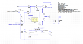
Dear Ben,what is the final schmatic has been used.
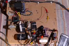
It's cooled off a bit, only about 25 degrees C so I decided to heat my room up a bit. Room heaters at 100W is the choked loaded 2SK180 follower for the left channel and at 200W is the mu-follower loaded THF-51S follower for the right channel. Additional heat provided by a Luminaria preamp and ACP+.
The ACP+ is used to amplify the signal from my TDA1541A dac. The dac has only a 75 Ohm I/V resistor converting a +/-2mA signal so maximum output is 0.15Vp.
All I can say is that I really like the sound. I haven't had the 2SK180 followers in my system for a while because of the heat, so my memory is weak, but as far as I can tell, this THF-51s follower amp sounds just like the 2SK180 follower. There is a clarity to the sound. Individual instruments and voices are distinct, and bass is good. There is a sense of realism. Now this is with the 2SK180 on one channel and the THF-51S on the other channel so it is not a 100 percent mu-follower THF-51S follower sound. So this is only a conditional opinion.
Now to build the left channel.

Here:
Single Ended Tokin SIT THF-51S Common Drain Mu Follower Amplifier , 45W?
I really like the sound but they are definitely room heaters, so the 2SK180 choke loaded follower is back in the system until the weather cools off. The THF-51S Mu follower will be my winter amp and auxiliary room heater.
In my system both the THF-51S Mu Follower and the 2SK180 choke loaded follower are winners.
For builders that don't want to create their own boards, Zen Mod's Lazy Singing Bush is the Mu Follower circuit concept on boards with the added bonus of an input buffer:
Single Ended Tokin SIT THF-51S Common Drain Mu Follower Amplifier , 45W?
By the way, the last schematic has only some changes in resistor values in the gate voltage circuit for the CCS and for adjusting the gate voltage of the THF-51S. I redrew the schematic to reflect the layout of the components on my board as an aid for me when I was putting the circuit together on the strip board.
Single Ended Tokin SIT THF-51S Common Drain Mu Follower Amplifier , 45W?
I really like the sound but they are definitely room heaters, so the 2SK180 choke loaded follower is back in the system until the weather cools off. The THF-51S Mu follower will be my winter amp and auxiliary room heater.
In my system both the THF-51S Mu Follower and the 2SK180 choke loaded follower are winners.
For builders that don't want to create their own boards, Zen Mod's Lazy Singing Bush is the Mu Follower circuit concept on boards with the added bonus of an input buffer:
Single Ended Tokin SIT THF-51S Common Drain Mu Follower Amplifier , 45W?
By the way, the last schematic has only some changes in resistor values in the gate voltage circuit for the CCS and for adjusting the gate voltage of the THF-51S. I redrew the schematic to reflect the layout of the components on my board as an aid for me when I was putting the circuit together on the strip board.
Last edited:
Here is an update on the distortion measurements. I cobbled together a voltage gain stage using a Russian KP926B SIT and used it to provide a high voltage signal to the amplifier. The gain stage is still in its early stages, assembled on a piece of wood and powered by a temporary power supply in Version 1 and Version 2, and by a lab supply in Version 3. It is still not where I would like it to be, with big issues, so more work needs to be done. Unfortunately my lab supply stopped working so I need to fix it, and hopefully I can, before I continue with my experimenting.
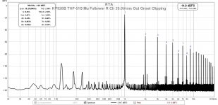
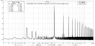
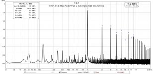
But I could get a decent 1000Hz signal amplified by Version 2 so I used it to test the THF-51S mu follower to clipping. The voltage gain stage had somewhere between 0.4 and 0.5% THD at the 20+Vrms output to get the amplifier to clip.
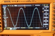
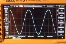
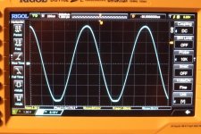
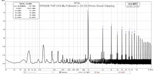
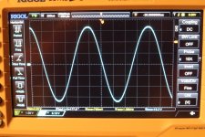
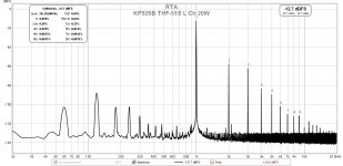
The left channel amplifier managed to output 19.2Vrms into 8 Ohms (46.1W 1.45% THD) without visible signs of clipping on my oscilloscope. At 20.0Vrms (50W 1.85% THD) clipping was clearly visible. The right channel managed 19.5Vrms (47.5W 1.93% THD) without visible signs of clipping, and at 20.0Vrms (50W 2.16% THD) clipping was visible. So the numbers were reasonable and THD was approximately 2% at maximum power output into 8 Ohms.
And now a story about how I found a major mistake in the wiring of one amplifier channel that I was not even aware of. I built the right channel first and did extensive testing before listening to it. When I finished the left I just did a distortion measurement at 1W. The THD was 0.070% so it looked good. I put both monoblocks into my system and listened for a couple of days, and I was happy with the sound.
So when I decided to test the amps with the voltage gain stage, I connected the gain stage to the left channel monoblock, hooked up the test equipment, and started the testing. To my surprise all I could get was a bit over 4Vrms out before I saw clipping. I checked the setup and connections and I couldn't find anything wrong. I disconnected the amp and tested the gain stage alone and it was good. I tested the amplifier alone with the oscillator, which only outputs low voltage, and it was good. I put everything back together and the same bad result. Of course it was wishful thinking on my part, expecting a different result. So I took out the left monoblock and connected the right monoblock to the gain stage, and the results were good.
So something was wrong with the left monoblock, even though the lW measurement and listening to it playing music did not lead me to think that something was wrong. I opened up the amplifier and started comparing the board and wiring to the schematic and found the major wiring error. And this was after I had probably double or tripled checked the wiring during construction.
I had connected the THF-51S backwards, common source instead of common drain, and sending V- to the drain. The THF-51S source was to Ground and the drain to the CCS. But it played music. Since I had only measured its THD at 1W, and since my speakers are quite sensitive so that not much power is required at normal listening levels, I was totally ignorant of my wiring mistake. If I had not done the latest measurements I might not have ever found this mistake.😀
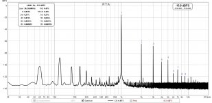
By the way the first plot is the Left channel at 10W output into 8R.
But I could get a decent 1000Hz signal amplified by Version 2 so I used it to test the THF-51S mu follower to clipping. The voltage gain stage had somewhere between 0.4 and 0.5% THD at the 20+Vrms output to get the amplifier to clip.
The left channel amplifier managed to output 19.2Vrms into 8 Ohms (46.1W 1.45% THD) without visible signs of clipping on my oscilloscope. At 20.0Vrms (50W 1.85% THD) clipping was clearly visible. The right channel managed 19.5Vrms (47.5W 1.93% THD) without visible signs of clipping, and at 20.0Vrms (50W 2.16% THD) clipping was visible. So the numbers were reasonable and THD was approximately 2% at maximum power output into 8 Ohms.
And now a story about how I found a major mistake in the wiring of one amplifier channel that I was not even aware of. I built the right channel first and did extensive testing before listening to it. When I finished the left I just did a distortion measurement at 1W. The THD was 0.070% so it looked good. I put both monoblocks into my system and listened for a couple of days, and I was happy with the sound.
So when I decided to test the amps with the voltage gain stage, I connected the gain stage to the left channel monoblock, hooked up the test equipment, and started the testing. To my surprise all I could get was a bit over 4Vrms out before I saw clipping. I checked the setup and connections and I couldn't find anything wrong. I disconnected the amp and tested the gain stage alone and it was good. I tested the amplifier alone with the oscillator, which only outputs low voltage, and it was good. I put everything back together and the same bad result. Of course it was wishful thinking on my part, expecting a different result. So I took out the left monoblock and connected the right monoblock to the gain stage, and the results were good.
So something was wrong with the left monoblock, even though the lW measurement and listening to it playing music did not lead me to think that something was wrong. I opened up the amplifier and started comparing the board and wiring to the schematic and found the major wiring error. And this was after I had probably double or tripled checked the wiring during construction.
I had connected the THF-51S backwards, common source instead of common drain, and sending V- to the drain. The THF-51S source was to Ground and the drain to the CCS. But it played music. Since I had only measured its THD at 1W, and since my speakers are quite sensitive so that not much power is required at normal listening levels, I was totally ignorant of my wiring mistake. If I had not done the latest measurements I might not have ever found this mistake.😀
By the way the first plot is the Left channel at 10W output into 8R.
Attachments
-
 KP926B THF-51S Mu follower R ch 8R clip 20.0Vrms.JPG723.8 KB · Views: 164
 -
 KP926B THF-51S Mu Follower R Ch Max Out 20.0Vrms Onset Clipping.jpg156.2 KB · Views: 161
 -
 KP926B THF-51S Mu follower R channel 8R 19.5Vrms.JPG732.2 KB · Views: 165
 -
 KP926B THF-51S Mu Follower R Ch Max Out 19.5Vrms.jpg152.4 KB · Views: 154
 -
 KP926B THF-51S Mu follower L ch 8R clip 20.0Vrms.JPG689.3 KB · Views: 160
 -
 KP926B THF-51S Mu Follower L Ch Max Out 20.0Vrms Onset Clipping.jpg156.4 KB · Views: 152
 -
 KP926B THF-51S Mu follower L ch 8R 19.2Vrms.JPG715.7 KB · Views: 569
 -
 KP926B THF-51S Mu Follower L Ch Max Out 19.2Vrms.jpg153.3 KB · Views: 575
 -
 KP926B THF-51S Mu Follower L Ch 8R 20W.jpg147.1 KB · Views: 587
 -
 KP926B THF-51S Mu Follower L Ch 8R 10W.jpg141.7 KB · Views: 609
Last edited:
so, now we have another confirmation how buggers are robust ......
have some elevator around, to try them with?

have some elevator around, to try them with?
Ben, looking good. Is the power supply noise attributed to the voltage stage PSU? Or was the some other change made to the amp PSU?
ZM, Yep, quite robust. I was sending 3A at 33V through the THF-51S backwards. The "UP" elevator was going down but fortunately there were no fatalities. 😀
Cody, That was probably due to the kludged temporary power supply and "bread board" construction of the V2 gain stage. Parts were whatever I had laying around, mostly from my tube days. And wires everywhere, including the source resistor connected with long clip leads for easy bias change.
Cody, That was probably due to the kludged temporary power supply and "bread board" construction of the V2 gain stage. Parts were whatever I had laying around, mostly from my tube days. And wires everywhere, including the source resistor connected with long clip leads for easy bias change.
Attachments
#108 ...
What!? No "Fugly" from ZM? 😀
Fantastic thread continuation. Good to know how robust these parts are.
What!? No "Fugly" from ZM? 😀
Fantastic thread continuation. Good to know how robust these parts are.
knowing Ben, it'll evolve in something ( at least looking) better ....... meaning - not prototype Fugly!
so, Fugly! reserved for most Fugly!
🙂
so, Fugly! reserved for most Fugly!
🙂
ZM, Yep, quite robust. I was sending 3A at 33V through the THF-51S backwards. The "UP" elevator was going down but fortunately there were no fatalities. 😀
I have had similar experiences with the 2SK182ES in my SIT3X. I have blown up several IXYS hocky-puck NFETs in the output stage but have never had problems with the SITs. They appear to be armored like battlefield tanks.
Here is an update
So when I decided to test the amps with the voltage gain stage.
I had connected the THF-51S backwards, common source instead of common drain, and sending V- to the drain. The THF-51S source was to Ground and the drain to the CCS. But it played music. — I was totally ignorant of my wiring mistake. .😀. .
I have had the same stupid mistake 🙄 with a 2SK60; for a gain stage. A luminous idea 😀. I thought . . . Some way it “amplified” 0,98*, ie was running as source follower. I already was holding the hand above the wastebin. Untill I thought - retest the resistances. And that was good.
I am still not sure if the pin connections are as they should be, havent done anything yet as next step …

...I had connected the THF-51S backwards...
Small J-FETs are essentially symmetrical. S and D may be interchanged. Some datasheets say so. A few have slightly different capacitance one way or the other, so for radio there is a preferred S and D.
The THF-51S is built different from small FETs but looks to be nearly symmetric. The main difference would be that the heat appears in the volume working as "drain", which in upside-down use has a longer thermal path to the heatsink so will run hotter.
1974 - A static induction transistor (SIT) Yamaha
Attachments

I will take pride knowing the sits I own were removed from elevator service and no one died.
Bill
Bill
- Home
- Amplifiers
- Pass Labs
- Single Ended Tokin SIT THF-51S Common Drain Mu Follower Amplifier, 45W?