kenpeter said:And making the output and feedback center nodes connect
does seem to reduce 1W distortion with no bad side effects.
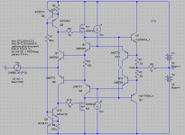
Blend under test today: roughly 1/3 Hawksford, 2/3 Allison...
No component changes necessary from the previous schematic.
Though I have found that both R5's of my bootstrap could easily
be increased to about 1K8 without starving the active current
sources. It has a negligible effect on distortion, but may let the
TO92 parts run cooler...
I've also messed with a secondary set of output transistors
outside feedback, just to pump the bootstraps only... This also
had a surprisingly negligible benefit, no way to justify the extra
parts....
Can you give some results into real loads / powers say
20V pk / 4R / 20kHz.
I don't seem to be getting much better results than plain
open loop EF.
cheers
T
Well, I will refrain from posting here out because my untested ideas only contribute to clutter here on the forums. Once I get new transistors I will commence real-life testing.
Kenpeter and others, I wish you luck with your projects.
Kenpeter, I respect your ideas and I have borrowed inspiration from them sometimes, but since your design goals are a little different than mine I propose that you should start a new thread devoted to your ideas. This way there will be less confusion between your ideas and mine.
Good luck,
- keantoken
Terry Demol said:
Can you give some results into real loads / powers say
20V pk / 4R / 20kHz.
I don't seem to be getting much better results than plain
open loop EF.
cheers
T
A friend Emailed me with similar results. It doesn't seem that using a follower buffer after the Allison without putting the outputs somewhere in the loop is very healthy for THD. His amplifier performed better with just Darlington+Vbe multiplier.
But I would have to test this with class A as well as AB - his amplifier was running AB.
I thought that the Allison had very, very low output impedance but after Kenpeter brought this up I saw the light after some thinking. The Allison has an output impedance of one of the bias resistors halved. So if you use .52 ohm bias resistors, your output impedance will be about .255 ohms. I'm not sure how this compares to a simple Darlington+Vbe multiplier.
- keantoken
Okay, here is something worth saying regarding output impedance.
The output impedance of a complimentary output stage will be determined by its quiescent current - that is to say, after you have pushed one transistor to the turn-off point your output voltage will be around .6V.
So if I bias an output stage at 1A, and push in 1A, I will have about .6V offset because one transistor has turned off.
Maybe you can see now that an output stage biased at 500mA will have twice the output impedance of one biased at 1A.
The same applies for the Allison, and for this reason an Allison - based output stage will have the same output impedance of a Darlington Class A set at the same bias current.
For this reason, Kenpeter, I suspect your Allison/Hawksford hybrid will have just as much output impedance as as a darlington Allison using the same bias current. I haven't tested this in the simulator.
Also, I never got a working version of your Email address (why don't you mail it to me?). I meant it when I said I could send you something useful.
- keantoken
Output impedance is not so much a quiescent event.
It is the slope of the error after all active corrections.
Negative feedback from the center point (Hawksford)
would definitely change the active slope of that curve.
Your equations might be right for uncorrected emitter
follower stages? I'm not ready to challenge that math.
I'm not sure why separate threads are helpful, unless
you prefer monologue blogging to an open discussion.
But I'll make this my last post and get out of your way.
kenpeter said:
I'm not sure why separate threads are helpful, unless
you prefer monologue blogging to an open discussion.
But I'll make this my last post and get out of your way.
It was my last intention to be rude, and I'm sorry if I offended you. This was exactly the reason I wanted to stop posting - I can go on and on about all my theories and things but I've realized it's no use and I should wait until reality arrives at my doorstop and I can begin work in a non-virtual environment.
I will be honest.
When you began posting your variations on the Allison, I was at once delighted and horrified - I wanted no less than absolute perfection and you were "abusing" my ideas by adding practical features such as smooth clipping etc. - I was not ready for that.
While I might be apprehensive to new ideas or someone else's take on my work (and/or the work of those I copy), I do my best not to be totally ignorant of what there is to learn.
The features you add are typically used by people who have experienced reality - something I lack. Since I don't know about all the awful things that happen in reality I don't trust my own judgment when it comes to correcting and anticipating for them. As I've played in the virtual world of the simulator I've developed (and still work on) a good theoretical base, so I'm more than sure of myself when I post my findings (maybe I'm overconfident, but when someone challenges me I always inspect their argument).
My intention was not to put a stopper on constructive conversation. I am interested in your work and planned on following your thread if you chose to make one. I thought it would simply be better to keep our work more separate because we have a different take on things.
I want you to keep posting. Based on my arguments I want you to use your best judgment on whether or not you should keep posting in this thread or go somewhere else - I say this because I no longer trust my own judgment on the matter.
What I do know is that there aren't many willing to talk to you about your Allison derivatives, and if anything I am entirely willing to give you what input I can regarding them. I have been giving my own ideas more merit than yours because I wasn't very interested in anything with THD above .004%. Now that I realize how wrong this is, I am putting my own ideas in the backyard and would rather look at other things for a while. Needless to say I will put more thought into your circuits.
Also, you should know that even though I pretend to know things, I'm only 15 years old. Maybe with that knowledge you will understand better what to expect.
Output impedance is not so much a quiescent event.
It is the slope of the error after all active corrections.
Negative feedback from the center point (Hawksford)
would definitely change the active slope of that curve.
Your equations might be right for uncorrected emitter
follower stages? I'm not ready to challenge that math.
I wasn't speaking for Hawksford stages, and I don't know if it applies to them (I think it should apply to your circuit, but I could certainly be wrong). I know the same rule applies for the Allison, even though the underlying mechanisms are different.
My use of bold text was nothing but an attempt emphasize something important for those not willing to read every single post. I'm sorry if I offended you.
Regards,
- keantoken
Perhaps I have misunderstood. Felt accused of threadjacking.
All I was trying to do was brainstorm along very similar lines
to those you had presented. Couldn't find where I had gone
seriously off topic other than not plagiarize your ideas verbatim.
We are obviously not working on two exactly identical designs,
I don't think you will find two thought process more compatible.
If we thought entirely inside the same box, would be a lot less
useful in terms of spotting something the other might miss.
Nobody else is working on anything remotely similar...
I am a test bench technician. Class-D chip amps mostly these
days, nothing that requires knowing anything but to follow a
pre-written (by someone else) test procedure. I rarely ever
am encouraged to work on my own ideas, like almost never...
I'm not trained or degreed as an engineer. You know SPICE
far better than I do, still playing catchup. Could care less if
you were 15 minutes old, an anvil, or a robot. If new ideas
keep coming (even unpolished ones), I don't care from where...
Just stop whining how your junk is cluttering up the place.
If your untested ideas were useless, I wouldn't be reading.
My own ideas are not any better tested, nor higher in merit.
Okay. Thank you for understanding.
Now that we understand each other better, we can work more closely.
There are a few good ideas I have that I plan on testing before I post, just so I'll be able to catch the attention of others maybe enough to get someone else to test my idea and give feedback. This is crucial since I don't have any precise audio equipment that others do (and I suspect I will end up building all my equipment until I have the money to buy it).
- keantoken
2N5771 and 2N5769 SPICE models, improved.
I found the current LTSpice models for the 2N5771/5769 to be very bad.
I corrected them to the best of my ability, these should be more accurate.
Beta begins to roll off at 2mA, which will be more accurate in VAS simulations.
Anyone is free to reality-check them. I borrowed parameters between them, so they're a bit more complimentary than I think can be expected. This is the last of my concerns because if you were using the previous models you might as well have been using completely different transistors.
.model 2N5769 NPN(Is=44.14f Xti=3 Eg=1.11 Vaf=100 Bf=78.32 Ne=1.389
+ Ise=91.95f Ikf=50m Xtb=1.5 Br=1.365 Nc=2 Isc=0 Ikr=0 Rc=.6
+ Cjc=2.83p Mjc=86.19m Vjc=.75 Fc=.5 Cje=4.5p Mje=.2418 Vje=.75
+ Tr=1.073u Tf=227.6p Itf=.3 Vtf=4 Xtf=4 Rb=10 Vceo=15 Icrating=200m mfg=Fairchild)
.model 2N5771 PNP(Is=44.1f Xti=3 Eg=1.11 Vaf=100 Bf=76.77 Ne=1.389 Ise=91.95f
+ Ikf=50m Xtb=1.5 Br=1.365 Nc=2 Isc=0 Ikr=0 Rc=3.75 Cjc=2.77p
+ Mjc=.1416 Vjc=.75 Fc=.5 Cje=2.65p Mje=.3083 Vje=.75 Tr=4.033n
+ Tf=118.5p Itf=.5 Vtf=3 Xtf=6 Rb=10 Vceo=15 Icrating=200m mfg=Fairchild)
I only corrected them at DC, so they might be (and probably are) off on their AC characteristics.
- keantoken
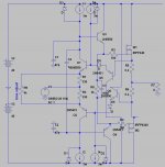
I think I should revisit post number 65: I did not give this idea enough thought and so I hastily assumed it could not work. This is untrue.
Looking back I realized I used a darlington configuration even with the MOSFETs, which is indeed overkill and wasn't helping stability any.
Here is a more stable idea, which works just as well as the Allison MOSFET version I first posted, but with less output impedance.
- keantoken
Looking back I realized I used a darlington configuration even with the MOSFETs, which is indeed overkill and wasn't helping stability any.
Here is a more stable idea, which works just as well as the Allison MOSFET version I first posted, but with less output impedance.
- keantoken
Attachments
keantoken,
I don't agree with the changes you made to the 2N5679. If anything, I would reduce Ise. Is seems a little low on the 2N5771, but don't make Ise quite so large. BTW, these transistors are only rated at 15 volts.
Rick
I don't agree with the changes you made to the 2N5679. If anything, I would reduce Ise. Is seems a little low on the 2N5771, but don't make Ise quite so large. BTW, these transistors are only rated at 15 volts.
Rick
sawreyrw said:keantoken,
I don't agree with the changes you made to the 2N5679. If anything, I would reduce Ise. Is seems a little low on the 2N5771, but don't make Ise quite so large. BTW, these transistors are only rated at 15 volts.
Rick
In the circuits I've posted here, those transistors operate within their voltage limits because Vce can be no greater than the Vbe or Vgs of the drivers and outputs. I am aware of the voltage limits for these transistors, which is why I don't use them so much.
I don't see what is wrong with Ise. The beta arcs at 2ma, just like in the datasheet, and then rolls off. If I understand correctly this parameter only affects Hfe and Vbe vs Ic, and when I check the models on the simulator the Hfe and Vbe curves look fine to me. Can you clarify?
Thanks,
- keantoken
Keantoken
I must say I am impressed on how fast you learn how things work!
To the topic: it seems to me, that this sort of output stage is self biasing the output devices to around 2A (one diode drop divided by 0R33 resistor).
Have you considered JFETs for the input so that it is possible to set lower bias?
I must say I am impressed on how fast you learn how things work!
To the topic: it seems to me, that this sort of output stage is self biasing the output devices to around 2A (one diode drop divided by 0R33 resistor).
Have you considered JFETs for the input so that it is possible to set lower bias?
darkfenriz said:Keantoken
I must say I am impressed on how fast you learn how things work!
To the topic: it seems to me, that this sort of output stage is self biasing the output devices to around 2A (one diode drop divided by 0R33 resistor).
Have you considered JFETs for the input so that it is possible to set lower bias?
Thank you. I am glad I can learn fast too.
Kenpeter has done some experimenting with Jfets to lower bias, schematics of which he has posted in one of my threads as well as here (I think).
I think trying Jfets is a good idea, but I am sure distortion will suffer and stability might be tricky because of the parasitics. Also, since Jfets vary significantly between devices, it may take some matching to get a pair with low output offset. (Note: in my current simulation, it seems matching of Jfets is crucial to the THD performance of the Allison)
I will be experimenting in the simulator.
But, but, I can't build these even if they work well in the simulator, because I don't have the parts. So any real-life testing will have to be done by someone else, at least until I have a pretty good stash of my preferred parts.
- keantoken
Surely you know someone who drives through Dallas regularly?
I can fix you up a bucket of parts suitable to your purpose.
-----------------------------------
Comparator VCE might never exceed the base threshold of the
next BJT in an Allison. But VGS-on if using a MOSFET, may need
a Zenier. If the amp is clipping, the comparator will try to swing
to the far limit of available bootstrap.
kenpeter said:Surely you know someone who drives through Dallas regularly?
I can fix you up a bucket of parts suitable to your purpose.
-----------------------------------
Comparator VCE might never exceed the base threshold of the
next BJT in an Allison. But VGS-on if using a MOSFET, may need
a Zenier. If the amp is clipping, the comparator will try to swing
to the far limit of available bootstrap.
I might know someone, not sure. I know someone who drives to the local TI plant every day, and sometimes goes to fry's.
I wonder if a simple resistor would work to provide the voltage drop instead of a zener? I will test in the sim.
- keantoken
darkfenriz said:Have you considered JFETs for the input so that it is possible to set lower bias?
Was this the one?
Since its about impossible that N and P Jfets will ever be exact
compliments. But you can get a matched pair N's, and matched
pair Ps. Put them in series, source to source. You now have two
matching quasi-comps that can be used to detect thresholds of
either polarity. And the resistors in the middle can trim out any
remaining difference.
Other types of junctions with fixed drop: Germanium, Schottky,
LED may also let you predictably trim your quiescent offsets to
something other than a multiple of a silicon emitter. You never
know the exact threshold of a JFET till you hold it in your hand
and measure it.
Attachments
- Home
- Amplifiers
- Solid State
- Simulation Analysis of several unique Allison-based output stages.