You can even simulate it as series 50/60 Hz sine sources, center-node grounded, with resistance in series with each, going through a FULL BRIDGE RECTIFIER and a bank of large caps, modeled with ESR (and possibly ESL).
Depends on the purpose of the modeling. Seeing how the amp behaves, or deciding how much supply cap you need.
Depends on the purpose of the modeling. Seeing how the amp behaves, or deciding how much supply cap you need.
Come to think of it, I have done that too. But at the time I was interested in startup transients and latch-up issues.
A trickier problem is simulating a square wave input without messing up initial conditions, because the AC square wave is never zero volts (@zero time). I see a lot of simulations that short the coupling caps for this reason. Any better solutions?
A trickier problem is simulating a square wave input without messing up initial conditions, because the AC square wave is never zero volts (@zero time). I see a lot of simulations that short the coupling caps for this reason. Any better solutions?
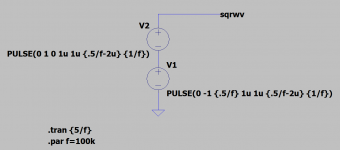
I assume that you are looking for a square pulse train with the very first halfwave of 50% duration. This eliminates slow cap charge setup. It should be doable with an initial delay of the pulse gen.
Come to think of it, I have done that too. But at the time I was interested in startup transients and latch-up issues.
A trickier problem is simulating a square wave input without messing up initial conditions, because the AC square wave is never zero volts (@zero time). I see a lot of simulations that short the coupling caps for this reason. Any better solutions?
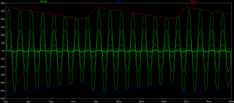
Set two square wave sources in opposition:
v1 middle top PULSE 0 5 0 1u 1u 499u 1m
v2 middle bot PULSE 0 -5 0 1u 1u 499u 1m
This gives a 1 kHz, 10 Vpp square wave that begins and ends each period at 0 V.
That way, the initial voltage is zero instead of -10, letting your coupling cap have the correct initial value. You can also set a .ic, but that can be a bit fussy.
If you use sine voltage sources for the rails you can choose a frequency and amplitude and then measure the PSRR for that frequency directly - just be sure the rail frequency(s) and signal frequency are not harmonics or each other. Using different frequencies for each rail allows the PSRR to be measured independently for the two rails.
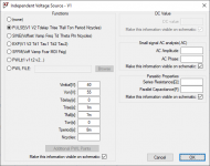
Sorry if might have a slow day but I can´t follow why you´d want to use a pulse and where are the sine waves coming from that you´re showing? Where´s V(out) in your schematic?An easy way in LTC Spice to simulate Power supply ripple is to use the pulse definition in the voltage source.
I always use sine waves for ripple sims as that´s what´s coming out of the transformer, right?
- Home
- Amplifiers
- Solid State
- Simulating supply ripple