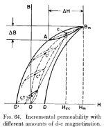
50AE, my view is that the BH curve shape for a swinging choke is not the commonly seen rectangular shaped hysteresis curve (as partly seen in post #9) showing a mainly linear central section, and then a clear knee section as the BH loci enters what is commonly identified as its saturation region of operation. I see the BH hysteresis curve as continuously varying from the origin out to extreme saturation region, and that the voltage induced operating loop/ellipse would not extend from near the origin and out into the saturation region, but rather be a more minor loop/ellipse in shape, although still a significantly sized loop/ellipse (compared to say in a CLC filter where the applied voltage is down at the volts or low tens of volts level). The most illustrative diagram I could find is attached from 1955 Lee 'Electronic transformers and circuits' book.
As such, operation at low DC current (but more than critical current level) may be illustrated by loop CII, and the loop does not extend into the 'saturation' region of the BH curve. For DC current below critical level, part of the loop is constrained by rectifier commutation to not extend into the lower two quadrants of BH plot, but does have some portion of the loop influencing the choke waveform.
I'd suggest the ac voltage across a swinging choke is fairly constant in magnitude, and doesn't significantly diminish for higher (but normal) dc current levels into a load. The attached diagram illustrates that situation, where it is the changing incremental inductance (slope of the loop) that is varying for larger DC load current conditions.
Attachments
Hi Trobbins,
Thanks for attaching this. We can observe the variation in slope (permeability) vs different DC excitation levels. But also, the amount of airgapping will affect the final result, such as linearizing the BH curve. Also, I have a variety of core materials around to play with, having different shapes of BH curves.
Thanks for attaching this. We can observe the variation in slope (permeability) vs different DC excitation levels. But also, the amount of airgapping will affect the final result, such as linearizing the BH curve. Also, I have a variety of core materials around to play with, having different shapes of BH curves.
I haven't had the chance to inspect any confirmed vintage swinging chokes for how they approached their 'gapping'. References generally describe the gap design for swinging chokes as being intentionally narrower than for a typical choke design.
Only some choke catalogs presented data specifically for choke-input filter applications, and specifically with a 'swinging' tag, and would show two sets of inductance @ dc current ratings, where the largest dc current value is the rated (max) current for the choke, and the other value is typically 10% to 25% of rated. However, those stated inductances are typically for 10Vac, and so need to be adjusted for the application’s level of Vac, which was significantly higher.
Only some choke catalogs presented data specifically for choke-input filter applications, and specifically with a 'swinging' tag, and would show two sets of inductance @ dc current ratings, where the largest dc current value is the rated (max) current for the choke, and the other value is typically 10% to 25% of rated. However, those stated inductances are typically for 10Vac, and so need to be adjusted for the application’s level of Vac, which was significantly higher.
I made a quick and dirty test on a 19V transformer, a swinging choke having 33mH initial inductance and 100mH amplitude inductance. Saturation value is significantly lower. The saturation knee appears between 0.5 and 1A
After the rectifier + filter the no-load output voltage was 26.5V for both.
With a 200 ohm load the voltage falls to 17.1V for the AC case, and 18V for DC
With 100 ohm, the voltages are 14.7V for AC and 16V for DC
With 30 ohm, 10.5V in AC, 14.6V DC
20 ohm: 8.8V in AC, 13.66V in DC.
Conclusion, the traditional method looks stiffer and better regulated
You also have to take Rdc losses into account, which are a main factor.
Usually, psud2 gives excellent results over choke input regulation simulation.
However, it is hard to build low Rdc choke input supplies with low Rdc and no ringing.
This is the main reason I wish to try placing the choke into the AC domain, before the rectifier.
Usually, psud2 gives excellent results over choke input regulation simulation.
However, it is hard to build low Rdc choke input supplies with low Rdc and no ringing.
This is the main reason I wish to try placing the choke into the AC domain, before the rectifier.
In this case, the Rdc of both the inductor and transformer were ~1.5ohm.
Anyway, the same elements were used in the two situations to allow for a fair comparison
Anyway, the same elements were used in the two situations to allow for a fair comparison
So gentlemen, I tried the setup in practice.
I used a 230V - 2x36,5V 360VA transformer with 1.9R primary and 2x0.22R secondary, and a 434T 3.6cm2 Afe choke with 1.4Rdc.
The choke has a HiB core and reaches 1.6T @ 55Vrms.
I did a small and quick test, using no rectifier, just loading the secondary using resistor values. Unfortunately I do not pocess many high power resistors with different values, but I manages to take the following points.
63V secondary voltage @ 105mA (600R) load
65V secondary voltage @ 3,3A (21,42R) load
62.8V secondary voltage @ 7,85A (8R) load
You can observe that the rig peak slightly, then drops afterwards, probably due to transformer and choke Rdc taking over.
To be honest, I am surprised by the performance at the moment. The drawback is the saturating choke emitting noise. The choke core was not glued or potted, just for the sake of testing.
Last edited:
Can you clarify the circuit used please? Is the choke in series with two series connected secondaries, and in series with the load resistor? I assume the 'secondary voltage' measurement is across the two series connected secondaries.
Are you able to measure the voltage across the choke and across the load R, and estimate the choke inductance (assuming load R is a current sense resistor , and sinewave conditions, and including load and choke DCR conditions in the inductance calculation)?
PSUD2 can provide some estimation by using a CLC filter with very low C values, and a low on-voltage diode bridge, but the non-linear behaviour of actual parts compared to ideal sim parts, and the half-sine voltage across the choke, appear to have a significant effect.
Apologies, I forgot mentioning this. The choke is is series with the transformer's primary. The secondary was loaded via a resistive load. That's all.
I only did a quickie measurement as a start, only for the justification if it would be worth it to purse in this path.
For next time, I'll try giving more detailed measurements.
I only did a quickie measurement as a start, only for the justification if it would be worth it to purse in this path.
For next time, I'll try giving more detailed measurements.
What is the actual goal? A choke input supply can have significanly less radiated noise because the conduction angle is much longer (and a better power factor). But that requires good optimization and a large (expensive) chunk of iron and a pretty steady load, like class A. Possibly why it made sense in the days of field coil speakers.
Is it possible to model a magnetic amplifier inductor in LTspice? And then you need to find someone to make it. . .
Is it possible to model a magnetic amplifier inductor in LTspice? And then you need to find someone to make it. . .
In order to achieve good regulation for a class B amplifier, which is the case, a choke after the rectifier, as choke input, needs a low Rdc. However, this results into a high, resonating Q in the power supply region. To tame this, one needs ample amounts of capacitance, hundreds of mF.
This is the primary reason I would like ot place the choke before the rectifier, without added capacitors.
P.S. I forgot to add this circuitry was intended to simulate a solid state amplifier power supply and I posted this in the wrong section. Can a moderator move the thread to the appropriate category, please?
Last edited:
- Home
- Amplifiers
- Tubes / Valves
- Simulating a swinging choke / saturating choke