
Gotcha Salas answered in Valve Itch thread:
http://www..com/forums/analogue-source/140635-valve-itch-phono-257.html
Lost constant parameter: "It also has the Neumann constant so don't pay attention to beyond 20kHZ compliance with ours"
Works better diyAudio search than Google😀
http://www..com/forums/analogue-source/140635-valve-itch-phono-257.html
Lost constant parameter: "It also has the Neumann constant so don't pay attention to beyond 20kHZ compliance with ours"
Works better diyAudio search than Google😀
Attachments
Last edited:
Merlin,
if you read Williamson and adopt his a) version you get exact values for the Rs & Cs when the Source impedance is zero.
Now read Hagerman and you will see that the Williamson values exactly match the early version fig 2.
Hagerman then goes on to show how to correct for a non zero source impedance and comes up with the final values fig 6.
Compare those to what is in post 16606
All the formulae for deriving the non zero source impedance values are given.
You could turn these into a spreadsheet to ease the arithmetic.
Attachments
Last edited:
Merlin,
if you read Williamson and adopt his a) version you get exact values for the Rs & Cs when the Source impedance is zero.
Now read Hagerman and you will see that the Williamson values exactly match the early version fig 2.
Hagerman then goes on to show how to correct for a non zero source impedance and comes up with the final values fig 6.
Compare those to what is in post 16606
All the formulae for deriving the non zero source impedance values are given.
You could turn these into a spreadsheet to ease the arithmetic.
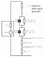
Thanks Andrew, is possible to mod the schematic for use 600R signal generator?
My 2 cents.
Reverse RIAA
http://www.diyaudio.com/forums/analogue-source/242855-mini-me-phono-preamp-3.html
I have a view left over, just send PM.
Reverse RIAA
http://www.diyaudio.com/forums/analogue-source/242855-mini-me-phono-preamp-3.html
I have a view left over, just send PM.
Attachments
Last edited:
Look at the Hagerman doc and check the formulae to see what the top resistor becomes when Rs=600ohms.Thanks Andrew, is possible to mod the schematic for use 600R signal generator?

I'm sorry Andrew, I can't see the formulae where is involved the source impedance of the signal generator.
page 5 saysI'm sorry Andrew, I can't see the formulae where is involved the source impedance of the signal generator.
And we can solve for R5
R5 = ....... when Rs= 50ohms
I think your capacitor ratios are wrong and that will give the wrong resistor values.For my schematic you can calculate R1 with R1=(3,18uS/C1\\C2)-680-imp.gen.
Check the numbers in the formulae.
Use Williamson for first guess to see if you are in the correct ballpark.
Here is a short write-up on inverse RIAA. I have tested it - good results.
An Accurate Inverse RIAA Network
An Accurate Inverse RIAA Network
I think your capacitor ratios are wrong and that will give the wrong resistor values.
Check the numbers in the formulae.
Use Williamson for first guess to see if you are in the correct ballpark.
I did my own calc and poles are within 1%. But most important this schematic is used more than hundred times to measure commercial and DIY phonostages. The ones who where in compliance with the inverse RIAA where always the best sounded stages. So get rid of your spice simulation and start to listen.
My signal generator has 50 Ohm intern resistance.
- Home
- Source & Line
- Analogue Source
- Simplistic NJFET RIAA