Realized the large output DCblocker could parasitically couple to the other channel's first DCblocker at input to 2nd NJFET. So I moved the EFI injection point to that signal chain node, as shown by big_open_arrow in Attachment. Crosstalk varies from 44.9dB SNR [such precision] at 20KHz, to 61.4dB SNR at 10Hz.
Does this crosstalk matter, if the cartridge channel-channel isolation sets the floor? probably not. On the other hand, if the crosstalk varies with frequency, will that cause the sound-stage [instrument position] to wander?
Here is the attachment.
I don't think they necessarily couple enough. Especially at its kind of output signal level (-10dBV). Depends on their construction and how their outer foil is oriented also. Haven't noticed wandering. Maybe build an FSP to listen to.
Keeping with your industrial capacitors theme I would recommend a couple of Vishay MKP1845 0.1uF axial polypropylene pulse grade capacitors that you can find on major stockists or on ebay....cut
Now acquired and installed. Thank you for your help and advice.
Graeme
That was fast. Found some locally? Did you notice any influence vs the very small white ones you used before?
That was fast. Found some locally? Did you notice any influence vs the very small white ones you used before?
Mouser/UPS were remarkably quick. A richer sound but the improvement was not the same order of magnitude as the change from the previous phono preamp to this design. The old one was a very simple design using two 2134 ICs and very basic (read not particularly accurate) RIAA correction.
I will repeat myself and say that I am extraordinarily pleased with this new build - I have even lashed out and supplemented my LP collection for the sheer enjoyment.
Graeme
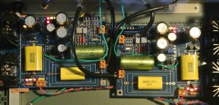
Good caps use is just about not holding it back. Its positive you unlocked some further richness. Did they fit well the C3 PCB room? Taken any photo? Circuitry matters most as always. You had a tube phono sometime also?
Predict & Reduce NanoVolt hum: 3 examples
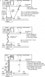
Some years back, a schematic appeared on my desk with question "What purpose have these 4 resistors" about a high-volume signal measurement application. We knew the customer would not install 4 resistors frivolously. Knowing the application, I soon computed the 4 resistors were injecting a nulling voltage of approximately 80 nanoVolts (or was it 300 nanoVolts?). The FieldApps Engr emphasized the measurements needed a zero-point calibration that was stable, or the customer could not achieve certification.
After a couple days, I realized the magnetic field of the 0.06 amp power supply current was injecting a small, computable, predictable error.
Hence the tool Signal Chain Explorer honors this discovery, with the HFI database entry "Power Meter Null Error".
As before, the simply math is
Vout = 2e-7 Henry/meter * (Area/Distance) * Current_Slewrate
Attachment#1 presents the 3 examples. You'll note the effort in Ex#2 to rescue the product by using 3-wire "twisted-pair". Unfortunately that effort brings the AggressorWire with its 60milliAmp current only 1mm away from our Loop.
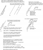
Attachment#2 details the 3_dimensional topology of the Signal Chain Explorer magnetic field (HFI) interference model. We assume the Wire and the Loop are in the same plane, such on PCBs. But moderately non-planar topologies can be easily approximated using the above math, just to get an idea of interference severity.
Some years back, a schematic appeared on my desk with question "What purpose have these 4 resistors" about a high-volume signal measurement application. We knew the customer would not install 4 resistors frivolously. Knowing the application, I soon computed the 4 resistors were injecting a nulling voltage of approximately 80 nanoVolts (or was it 300 nanoVolts?). The FieldApps Engr emphasized the measurements needed a zero-point calibration that was stable, or the customer could not achieve certification.
After a couple days, I realized the magnetic field of the 0.06 amp power supply current was injecting a small, computable, predictable error.
Hence the tool Signal Chain Explorer honors this discovery, with the HFI database entry "Power Meter Null Error".
As before, the simply math is
Vout = 2e-7 Henry/meter * (Area/Distance) * Current_Slewrate
Attachment#1 presents the 3 examples. You'll note the effort in Ex#2 to rescue the product by using 3-wire "twisted-pair". Unfortunately that effort brings the AggressorWire with its 60milliAmp current only 1mm away from our Loop.
Attachment#2 details the 3_dimensional topology of the Signal Chain Explorer magnetic field (HFI) interference model. We assume the Wire and the Loop are in the same plane, such on PCBs. But moderately non-planar topologies can be easily approximated using the above math, just to get an idea of interference severity.
Attachments
Good caps use is just about not holding it back. Its positive you unlocked some further richness. Did they fit well the C3 PCB room? Taken any photo? Circuitry matters most as always. You had a tube phono sometime also?
Tight squeeze but ok for fit. I also removed the surplus 1M resistor in R6.
While waiting for the group buy to eventuate and be delivered I built the phono preamp design from Merlin Blencowe's new book. This design uses PC97 and 12AU7 for each side and I cobbled it together on an old chassis and built it using locally sourced (cheap) components other than the valves which I had to get from Britain as PC97s were never used in any Australian made electronics as far as I could see. For all that this preamp does work extremely well and is very quiet. I think that the secret of its design is in the really good power supply approach taken by Blencowe, just as it is in your design. The Salas is definitely superior. I plan to duplicate the Blencowe using better componentry in the fullness of time to see if valves can match solid state.
Graeme
Attachments
Hi Salas, I already have your great phono running in my system, a friend of mine took his kit bought from Teabag to my place because he has one channel that show incorrect voltage. In particular Tp1-Tp2 stay firmly on 0,65V whatever I turn VR2 and VR1 and tension across R2 is 66,9mV while R3 and R2 and R3 in the correct channel are 90-91mV all resistor being 10,3ohm. Is it Q1 faulty?
See if R4 is the right value first. R13 Also. See about Q3 too. If it is the right part in the right position Q3Y or Q3Z, if it has normal Vbe (0.6V-0.7V). Looking for faulty Q1 or Q2 you could compare to the good channel ones (when with power off and let them cool down) by measuring their internal resistances between Drain and Source pins. But I don't think so, looks like some error or faulty part deprives their normal bias current which is spot on in the good channel by the way.
I checked the difference are in r10 and r13 in the faulty channel they are 1350 r10 and 1200 r13 the correct channel they are 725 and 630, talking of resistor soldered on the board. Out of the boards they are correct value. Checked q5 and q6 and they are ok like all othes semi. The regulator has problem too, raw supply is 50v I can't go lower than 45v with vr2.
I checked the difference are in r10 and r13 in the faulty channel they are 1350 r10 and 1200 r13 the correct channel they are 725 and 630, talking of resistor soldered on the board. Out of the boards they are correct value. Checked q5 and q6 and they are ok like all othes semi. The regulator has problem too, raw supply is 50v I can't go lower than 45v with vr2.
So the verified problem is the high rail. What voltage drop is there across R3x? When you tweak VR2x does it move at all even at high level only?
Cload, or length of output cable, affects SNR
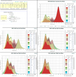
After modifying the Salas model to reflect the 2nd Rdrain (8Kohm) that defines Rout, and adding a final shunting capacitor Cload to model Cable capacity, I tried various Cload in Signal Chain Explorer.
From 0.1pF (very difficult to reach that low a value), to 1000pF, the Signal Noise Ratio varies 6dB, because low values of Cload permit a wide noise bandwidth.
Should we view this random noise as spikes, faster than the Power Amplifier can fully respond, then these spikes cause tiny Impulse Response waveforms to appear on the loudspeaker. Thus noise rolloff is needed.
I found a 400pF Cload [ Ccable + some Cdiscrete ] acting against Rout of 8Kohm, produced 50KHz bandwidth which should allow Moving Coil accuracy. And MM should also be fine with that output bandwidth?
800pF would produce 25KHz bandwidth.
Attachments
There is a buffer stage at the output. Rout is about 50 Ohm (FSP). Usual 1 meter coax IC cables will be about 110pF (terminated)
Hello Salas,
I just assemble the preamp and have a question about Q4, Q5 and Q6 transistors. I have the following values of 2SK170BL:
Q4 = 8,36 + 8,41 mA
Q5 = 7,51 + 7,51 mA
Q6 = 9,30 + 9,14 mA
I bought today new 2SK170BL's and IDSS of all new transistors are approximately 15-17 mA. I could select pairs e.g. 15,5+15,5 and 16,5 + 16,5 and 17,2 + 17,2 or similar.
Should I leave a lower values or choose the higher one?
--
Best regards
Pawel
I bought them from the shop, where I usually buy trasistors and had no problems before. In Toshiba datasheet there is information, that IDSS for 2SK170 is between 2.6 - 20mA, where GR grade range is 2.6-6.5, BL range 6-12mA and V for range 10-20mA.
Maybe not fake, but high grade IDSS, I hope 🙂
Maybe not fake, but high grade IDSS, I hope 🙂
Fake. There is no original 2SK170BL >12mA that I had ever encountered. Use the lower values Q4,Q5,Q6 selections you posted, they are good for those positions. Even if they were original V grade they wouldn't work right with the BOM standard surrounding resistors.
R3x is 40V. Rail stay at 50V and doesn't change with VR2X.
U
U
So the verified problem is the high rail. What voltage drop is there across R3x? When you tweak VR2x does it move at all even at high level only?
- Home
- Source & Line
- Analogue Source
- Simplistic NJFET RIAA