I reflowed the joint and nothing changed.
I am now getting 47V between ground and rail + with no adjustment on Vr2x. I did nothing but measure voltages on the different transistors, and from different transistors to rail and ground to try to find differences between boards.
must have shorted something...
I am now getting 47V between ground and rail + with no adjustment on Vr2x. I did nothing but measure voltages on the different transistors, and from different transistors to rail and ground to try to find differences between boards.
must have shorted something...
Last edited:
Something is wrong. Is there still 1.55V across R1x (100mA through) like before? Do you have spare MOSFET?
I getting less than 0.5V on R1x.
I checked my local parts shop, they have the irf9530 in stock.
edit: I have one from the BIB regulator kit, should I replace it?
I checked my local parts shop, they have the irf9530 in stock.
edit: I have one from the BIB regulator kit, should I replace it?
Last edited:
Normally you pull both MOSFETS out first and you check them with various methods. So you move to the other smaller semis if they are good. Buy two in case Q6x has a problem also.
From BIB are the same good MOSFET parts to borrow. But eventually you should use the recommended IRF9610 for Q1x. After fixed. Its a faster part good for the specific position. And of course the two channels should have the same semis in the end.
They are still P-MOS enhancement mode parts with different gm and parasitic capacitances that would basically work interchanged apart from changing the expected bias currents and the frequency performance. But if an oscillation occurred due to that, it could hold the Vout back or overheat a semi.That would be bad! But it happens! 🙂
Got the same issue check for Q4X it might be shorted.
Possible in the new problem description phase because before he reported good Vbe reading for it
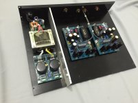
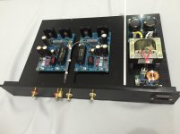
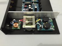
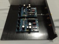
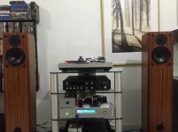
Nice sectioning and short AC cabling, nice signal cabling dressing also, but don't trust an aluminum section can stop hum field if intrusive. Mu metal or copper Gauss band shielded transformer and proper orientation are better. The distance seems good though and it *may* turn out fine. Easier to succeed when in MM or high MC mode, since its one JFET only I see in the input stage.
Hi Salas,
I'm using Ortofon OM RED so I followed the procedure the gain set-up for 5mV cart. I tried it on my system and it sounds good so I'm putting it in chassis now. Will wrap the trafo with copper sheet.
I'm using Ortofon OM RED so I followed the procedure the gain set-up for 5mV cart. I tried it on my system and it sounds good so I'm putting it in chassis now. Will wrap the trafo with copper sheet.
Attachments
Last edited:
You will soon get an itch for 2M bronze or black in that system, it seems evolved enough 😀
Are those speakers English?
Are those speakers English?
the speaker is Unity Audio CLA-1.
http://www.cerioustechnologies.com/pdf files/cla_lit.pdf
Salas this is my first Phono preamp, please bear with me if I will bother you sometimes.
http://www.cerioustechnologies.com/pdf files/cla_lit.pdf
Salas this is my first Phono preamp, please bear with me if I will bother you sometimes.
Will wrap the trafo with copper sheet.
Try it as it is first since MM gain is not too sensitive for hum pick up
- Home
- Source & Line
- Analogue Source
- Simplistic NJFET RIAA