Vifa drivers probably. Very well balanced speakers have been made with Vifa of old. But 300W power handling spec, yeah right.
The foam surround seems to have held well. Lived in dry climate room with grills on blocking direct sunlight?
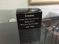
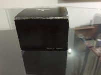
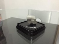
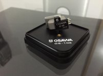
I have also an MC cart with 2mV output, If i fit this one do I need to change the Gain set-up again i.e. add transistors, change resistor values etc. or is it simply flipping those dip switches?
Attachments
The foam surround seems to have held well. Lived in dry climate room with grills on blocking direct sunlight?
With the age of the speakers you won't believe the drivers are still looks brand new. I traded my Paradigm and get this one. Well my friend is happy with my Paradigm and I'm happy with his Unity audio 😀😉
PS:
The mid and woofer fitted with rubber surround no signs of crack or imperfection it's still intact.
Last edited:
I have also an MC cart with 2mV output, If i fit this one do I need to change the Gain set-up again i.e. add transistors, change resistor values etc. or is it simply flipping those dip switches?
Optimal would be the 43dB high MC mode build but in the 40dB MM now the 2mV is still playable especially if there is some gain in the line level preamp
Ok, I have the mosfets in the right position, I got the names wrong.
I will replace the irf9610 on Q1x position and report back.
I will replace the irf9610 on Q1x position and report back.
So the problem was aparently Q3X. I replaced it and now I'm getting around 32V on the rail +. I'll see what I need to do to bring it up an extra volt or 2!
Nice you narrowed it down to the culprit eventuallySo the problem was aparently Q3X. I replaced it and now I'm getting around 32V on the rail +. I'll see what I need to do to bring it up an extra volt or 2!

Ok, I biased the boards to 3.6V on TP1-TP2. I connected everything and I am getting no sound on the left channel, the one with the "bad" board. So where should I start looking now?
Could the 47V across the entire board have damaged any of the circuit transistors?
Could the 47V across the entire board have damaged any of the circuit transistors?
They wouldn't have exceeded their max voltage but dissipation could have been stronger in the output stage ones. Look there first. DMM in Ohm mode should not show any as a short from its D to S pin (when powered down) else its damaged. 30-50 Ohm is more likely for the K170BLs and 10-30 Ohm for the K369BLs. Check also that there is continuity from your input RCA to the K369's gate. So to make sure its not in the wiring.
The 369 has the little heatsink in it so that would have helped with the dissipation figure.
I have continuity from rca in to 369 gate. And the resistances are in the ballpark you mentioned for both the 369 and 170's. ( q4, q5, q6)
I also have around 10V just before C4 so there is DC offset before the putput capacitor.
I have continuity from rca in to 369 gate. And the resistances are in the ballpark you mentioned for both the 369 and 170's. ( q4, q5, q6)
I also have around 10V just before C4 so there is DC offset before the putput capacitor.
Last edited:
All those things are measuring normally. Swap both channels in/out interconnects to exclude the problem is somewhere in the lines. If it will appear on the other channel then its located outside.
If no suspicion again, measure and compare all semiconductors drain to ground voltages between the live and the quiet channel
I swaped both channels and the problem appeared on the other speaker.
All the cables are good, as well as the preamp and amp.
I then connected the phono stage to the turntable and no cables on the output. Started playing a record and got:
Good board: variable mV AC between .1 and .4 V
Bad board: ~8V AC no variation.
All the cables are good, as well as the preamp and amp.
I then connected the phono stage to the turntable and no cables on the output. Started playing a record and got:
Good board: variable mV AC between .1 and .4 V
Bad board: ~8V AC no variation.
I finally found the problem and quite a simple and stupid one I should have checked earlier. A bad solder joint on the output rca. Old copper wire with oxidation... new wire and now I have sound coming out of both channels!
Wiring is for testing purposes only. I have some background noise without any music playing which is expectable at this moment.
Complimentary picture of my 2 days old pass labs F4! 🙂
Wiring is for testing purposes only. I have some background noise without any music playing which is expectable at this moment.
An externally hosted image should be here but it was not working when we last tested it.
Complimentary picture of my 2 days old pass labs F4! 🙂
An externally hosted image should be here but it was not working when we last tested it.
Last edited:
- Home
- Source & Line
- Analogue Source
- Simplistic NJFET RIAA