Make R10s 7.5K for bit more gain since your cart is 0.3mV and your rail is high enough
Hi
this worked a treat a nice uplift on the gain now can listen at lower volume
the FSP just keep getting better the more it gets used
here is pic`s in its case
Attachments
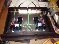
yes a naim case got lucky on ebay £50
just got to hook up the front panel needs 27vdc
might get a separate P/S for the job
just got to hook up the front panel needs 27vdc
might get a separate P/S for the job
You could tap off from one raw dc line to some properly dropping resistor or to an LM317 set at 27V.
That will be a trick Naim looking phono box with unusual sonic signature to any unsuspecting guest 😀
That will be a trick Naim looking phono box with unusual sonic signature to any unsuspecting guest 😀
I just got some new orange leds to complete my build. They were listed as 1.92vF which would have yielded the specified string values. It turns out they are fairly uniformly 1.8vF.
Are 3 and 4 strings of 5.4vF and 7.2vF ok for the FSP?
My RAW supply output voltage is a relatively low 43vDC, if that is relevant (I imagine it is).
Thanks
Are 3 and 4 strings of 5.4vF and 7.2vF ok for the FSP?
My RAW supply output voltage is a relatively low 43vDC, if that is relevant (I imagine it is).
Thanks
Both your achieved total Vf and RAW are fully workable in this circuit. Orange is a nice glowing hue also.
*The datasheet's nominal Led's Vf is for 20mA usually so its normal to find less at about 5mA. There is some I/Vf curve included in the manufacturer's data many times.
*The datasheet's nominal Led's Vf is for 20mA usually so its normal to find less at about 5mA. There is some I/Vf curve included in the manufacturer's data many times.
Both your achieved total Vf and RAW are fully workable in this circuit. Orange is a nice glowing hue also.
*The datasheet's nominal Led's Vf is for 20mA usually so its normal to find less at about 5mA. There is some I/Vf curve included in the manufacturer's data many times.
Ah yes, so the precise achievable Vf is determined by the current applied, yes? I'll try and get the strings well matched, and hope it translates at the higher current of the FSP.
I will fire it up asap....maybe tonight!
Thanks so much Salas!
The FSP runs through the Leds as much current as the in circuit associated JFET IDSS i.e. about 4-5mA. The battery and resistor matching test in the guide is devised to run 4-5mA so you can already be measuring Vf as in the circuit's reality ballpark 😉 Good luck with powering up tonight.
So, I sorted the led chains and finished soldering.
I connected the FSP to the raw power supply. No case yet, or rca connectors etc. Just the three boards and the starquad cable.
Powered up. All leds lit instantly.
Both voltages were between 34-36. TP1 TP2 was very low, like 2.3v on both channels. I lowered both VR2 until TP1/2 was exactly 3.6v, which resulted in 32v and 32.3v rails. A bit lower than the range you've mentioned Salas.
I haven't touched VR1 yet. I wasn't sure from the instructions what the idea was with VR1. They're still set in the middle of their range, give or take a half turn.
I've put it away for the night, as it's 3am. A good start though. No smoke or bangs is always good!
So far so good. 
VR1 is a secondary circuit branch control that can lower the voltage rail a little for the input stage only. By using VR2 alone you have control of the total rail voltage and many end up with voltages like yours without trouble. Some go higher, its about semiconductors tolerances. My prototype's LEDS and JFETS gave those numbers in the guide. Not written in stone if not too far off in yours. VR1 is no big deal to engage when the total rail does not have to go unusually low so to hinder the output stage's swing envelope getting it in possible peak overload territory.
VR1 is a secondary circuit branch control that can lower the voltage rail a little for the input stage only. By using VR2 alone you have control of the total rail voltage and many end up with voltages like yours without trouble. Some go higher, its about semiconductors tolerances. My prototype's LEDS and JFETS gave those numbers in the guide. Not written in stone if not too far off in yours. VR1 is no big deal to engage when the total rail does not have to go unusually low so to hinder the output stage's swing envelope getting it in possible peak overload territory.
Something clever just flew over my head! 🙂 Something about VR1 and the output's swing stage envelope.  That last line sounds like years of experience and knowledge compressed into one sentence. To explain, I'm sure you'd have to go back to basics and educate me.
So, next I think I'll build a wooden case for the FSP, lined with copper sheet I have. I am thinking rosewood, finger jointed, oil finish. We will have to wait longer though....the raw power supply already has it's case - a steel cash box, with a locking lid, like this:

That last line sounds like years of experience and knowledge compressed into one sentence. To explain, I'm sure you'd have to go back to basics and educate me.So, next I think I'll build a wooden case for the FSP, lined with copper sheet I have. I am thinking rosewood, finger jointed, oil finish. We will have to wait longer though....the raw power supply already has it's case - a steel cash box, with a locking lid, like this:
I will try to explain in more words. Q4 & Q5 got to have enough Rail+ so the voltage drops across their loads still leave them space to swing for non-squashed odd signal peaks. Say on a very loud record's peak passage or on clicks. Thus when in an unfortunate tolerances build we need drop Rail+ too much with VR2 (under 30-31V) to achieve correctly centered input stage TP1-TP2 reading, we better stop there and engage VR1 to drop the rail a little more only for the input stage. You will notice that after you got TP right with VR2 you can still change it with VR1.
P.S. Clever way to can "unlock power" for when replaying special recordings without hooking up an expensive power cord 😀
P.S. Clever way to can "unlock power" for when replaying special recordings without hooking up an expensive power cord 😀
I need advice. Looking for a small tabletop lamp to serve my turntable. I see those in use on some pictures on our forum. All what I own and tested by now made soundable noises through speakers. Halogen bulb based is particularly loud. Strange since it is linear 12v trany inside of it. Any thoughts... Thank you.
I use a few of these in an array for even illumination, I've also attached a photo of my listening area...
An externally hosted image should be here but it was not working when we last tested it.
IKEA has some interesting led lamps.
I use this one TIVED LED wall/clamp spotlight - IKEA and I have no noises whatsoever.
I use this one TIVED LED wall/clamp spotlight - IKEA and I have no noises whatsoever.
LED-lamps is best for less radiation from the lamp but the switching powesupplys sux. Make a linear tiny 12 v trafo-full wave rect-cap-7812 psu for the IKEA lamp. Wont work for 6L6 tho...
- Home
- Source & Line
- Analogue Source
- Simplistic NJFET RIAA