Very similar mass to my SME IV (11gr). They are high compliance carts, and should mate well with low and mid mass arms. You can of course use the various online calculators in order to predict the resonance frequency of the combination.
After a long long time I finally began assembling the FSP!

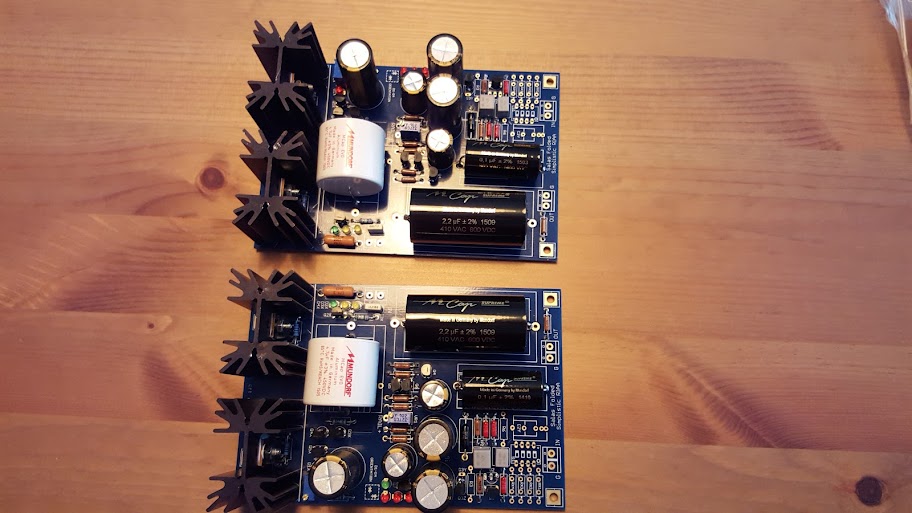
PRP resistors for R1, R14 and R5, vishay on the remaining positions. Mundorf Supreme capacitors for C3 and C4 are on the way.
10000uf capacitors on the raw supply and toroidy transformer will be used. Signal in will go directly to R1 without Rx resistors and switch.
One question. I have the little heatsinks for the 2sk369. Should I use thermal paste when mounting or is the simple contact between the metal and transistor enough?
Last edited:
Simple contact. Even better is a small plastic or paper box for them that creates a little "greenhouse" to keep them isolated from external temperature changes when they reach their own top temperature.
Simple contact. Even better is a small plastic or paper box for them that creates a little "greenhouse" to keep them isolated from external temperature changes when they reach their own top temperature.
So heatsink and then the plastic box to protect from outside temperature change.
Even without heatsink no problem. They don't dissipate anything much. Maybe the smaller housing possible is better.
Nice! I can use the heatsinks for my BA3 which might need some extra help taking the heat of the 2sj74/2sk170
Very similar mass to my SME IV (11gr). They are high compliance carts, and should mate well with low and mid mass arms. You can of course use the various online calculators in order to predict the resonance frequency of the combination.
Thank you for all this details. All fish one.
Let you know....
Sent from my iPhone using Tapatalk
I mounted an AT Art9 on a 16g Grace 940. I replaced the 12 g oem Grace headshell with an 8g, probably dropping eff mass to around 12g. No compliance/resonance issues noticed.
Boards are finished, now I must wait for the transformer to arrive, should be here in about 2 weeks! The wait... the wait...
Hi Salas,
I am busy populating my boards now. Very exciting! I have bought 2 lots of 20 of K117 GR now, and have a nice matched pair of 4.92mA for the RIAA circuit. For the shunts though, you are recommending 3-4mA, and out of the 40 I've bought, none are below 4mA, and some are as high as 6.08mA. I am testing with a 9.6v battery, however.
My lowest 6 are: 4.00, 4.24, 4.33, 4.34, 4.59, 4.78
What do you think I should do? Use them or buy some more?
By the way, they seem to stabilise in less than half a second, unlike K170s which are all over the place for several minutes and vary with temperature. Is that to be expected?
Many thanks
K117GR is officially 2.6mA-6.5mA IDSS range. Chancing on mainly strong ones is not impossible. The measurement stabilizing behavior between those types is like you described. You can use them in the shunts but post a close up clear photo of one sample if you can so we could confirm originality clues for you before you populate the PCBs with thoseHi Salas,
I am busy populating my boards now. Very exciting! I have bought 2 lots of 20 of K117 GR now, and have a nice matched pair of 4.92mA for the RIAA circuit. For the shunts though, you are recommending 3-4mA, and out of the 40 I've bought, none are below 4mA, and some are as high as 6.08mA. I am testing with a 9.6v battery, however.
My lowest 6 are: 4.00, 4.24, 4.33, 4.34, 4.59, 4.78
What do you think I should do? Use them or buy some more?
By the way, they seem to stabilise in less than half a second, unlike K170s which are all over the place for several minutes and vary with temperature. Is that to be expected?
Many thanks
From the guide
"*If batches of 2SK117GR are yielding circa 5mA IDSS then use 6.2K R3x 0.5W and 33R R6x"
Thus use the above resistors & ~5.5mA for your Q3x & Q2x, use the 4.33-4.34 you listed for Q5x
Thanks Salas,
It's so long since I compiled my BOM, I had forgotten that I've ordered and installed the correct resistor changes for 5mA K117GRs already! I've even posted pics to you to confirm that they're real ones....about a year ago now I think!
So, onwards! Many thanks again bro. You're quite the dude you know. I really appreciate it.
Lucas
My red LEDs are all 1.71x - All 40 of them. Tested with 9.6v battery and 1.8K resistor
1.71 x 3 = 5.13v
1.71 x 4 = 6.84v
Any good? Not the 7.75v and 5.8v you specify.
Is matching the strings the critical thing, or hitting specification voltages, or both?
Thanks again!
1.71 x 3 = 5.13v
1.71 x 4 = 6.84v
Any good? Not the 7.75v and 5.8v you specify.
Is matching the strings the critical thing, or hitting specification voltages, or both?
Thanks again!
Last edited:
Matching is priority but absolute voltage better be closer to recommendations. My original leds were rather high but yours are on the lower side than average. What happens if you combine a green one?
Also, check ebay vendor 2juki.
I found 2juki from Hong Kong. Is this is the guy to buy from?
Sent from my iPhone using Tapatalk
add a signal diode.My red LEDs are all 1.71x - All 40 of them. Tested with 9.6v battery and 1.8K resistor
1.71 x 3 = 5.13v
1.71 x 4 = 6.84v
Any good? Not the 7.75v and 5.8v you specify.
Is matching the strings the critical thing, or hitting specification voltages, or both?
Thanks again!
1n4148, or 1n914.
Gives 5.13V +~0.7V = ~5.83V & 6.84V +~0.7V = ~7.54V
All of those voltages can be trimmed by adjusting the current through the reference string. The source resistor is your adjuster
Thanks Andrew. I've ordered 30x 1.92vF leds now, which should hit the spot dead on, if they are within spec. These ones were clearly 1.7vF ones.
My red LEDs are all 1.71x - All 40 of them. Tested with 9.6v battery and 1.8K resistor
1.71 x 3 = 5.13v
1.71 x 4 = 6.84v
Any good? Not the 7.75v and 5.8v you specify.
Is matching the strings the critical thing, or hitting specification voltages, or both?
Thanks again!
My red leds were on the low side too. I used one green + two yellow for the 5.8V and two green + two red for the 7.75V.
Be wary of using higher Vf LEDs. I have a feeling that higher voltage risks higher noise.
I don't know how to check the effective noise of a voltage reference string.
Take a 3off 1.92Vf giving 5.76Vref and compare to 3off 1.7Vf + 0.66Vf(1n4148) also giving 5.76Vref
Which is quieter?
Which has lower dynamic impedance, (slope of the I vs V line)?
I don't know how to check the effective noise of a voltage reference string.
Take a 3off 1.92Vf giving 5.76Vref and compare to 3off 1.7Vf + 0.66Vf(1n4148) also giving 5.76Vref
Which is quieter?
Which has lower dynamic impedance, (slope of the I vs V line)?
- Home
- Source & Line
- Analogue Source
- Simplistic NJFET RIAA