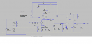
IMO, we can leave R12 as 100ohm and also C6 just to filter the rail, but the trimming action must be placed in the DNMOS source resistor..... Due to differences in Idss, we will need a trimmer to set the correct current to bias the folded cascode.
Nice one Salas .... once again I have some mods to do 🙂
Nice one Salas .... once again I have some mods to do 🙂
Been simulating the R3 Mod with the Supertex depletion mode mosfet and found that with a CCS instead of R3, VR1 trimmer action is irrelevant.
Once we find the correct CCS current as to bias the folded half way, trimming R12 only changes Vds in the DNMOS..... It might change something sonically but does nothing in biasing terms.
Maybe we could also do without C6 if using the ccs ...?
Are you speaking of R3 or R13? I think the later, if not I'm confused.
ps Are you using 4.7 uF in the output? Have you more low bass ?
Thanks
Are you speaking of R3 or R13? I think the later, if not I'm confused.
ps Are you using 4.7 uF in the output? Have you more low bass ?
Thanks
Sorry .... R13 it is indeed.
I am using 4.7uf in the output because my preamp sports 10kohm input impedance..... I would loose bass otherwise..... Anyway I believe there is less phase shift using bigger output caps 🙂
Salas congrats for the FSP, very easy to do the kit, also congrats to crt for the layout and finally tea-bag to support the GB.
Been simulating the R3 Mod with the Supertex depletion mode mosfet and found that with a CCS instead of R3, VR1 trimmer action is irrelevant.
Once we find the correct CCS current as to bias the folded half way, trimming R12 only changes Vds in the DNMOS..... It might change something sonically but does nothing in biasing terms.
Maybe we could also do without C6 if using the ccs ...?
Better vary R20 instead. Keep the cap.
Salas congrats for the FSP, very easy to do the kit, also congrats to crt for the layout and finally tea-bag to support the GB.
I tormented both with my strict directions about guided layout and parts selections, so they deserve kudos.
Now with a stiffer CCS..... this one might sound good 🙂
It will reject better the rail but it will inject some extra current noise too. Listen carefully for tradeoffs.
Really really a piece of cake and a pleasure making the FSP, plenty of power, a lot of detail, a new beast is born to let us enjoy our vinyl treasures.
where is R20?😕
In his particular simulation. Meaning his source resistor for depletion Mosfet. Can vary that CCS current.
where is R20?😕
R20 is the source resistor in the new CCS (in my simulation it is numbered R20)
Really really a piece of cake and a pleasure making the FSP, plenty of power, a lot of detail, a new beast is born to let us enjoy our vinyl treasures.

R20 is the source resistor in the new CCS (in my simulation it is numbered R20)
Run FFT with input signal good for -10dB output which is the normal for this. I will tell you if it ties with reality bcs I had run real FFT in many builds.
It will reject better the rail but it will inject some extra current noise too. Listen carefully for tradeoffs.
Will try a noise analisys before implementation.
Can we get lower noise with bjt CCS ?
Will try a noise analisys before implementation.
Can we get lower noise with bjt CCS ?
Not sure, it depends on rbb' and bias current. You would need genuine low noise BJTs that can take the dissipation also.

Merlino, are you running single ended or balanced?
Ciao Orelli, now SE but due to the high SQ I'm thinking to go balanced in the future.
- Home
- Source & Line
- Analogue Source
- Simplistic NJFET RIAA