 Now with your aligned to mouse quiet Lenco motor, expectations grew higher.
Fit longer flexible output and mains leads. Keep the pairs twisted.
Place the EI transformer near the amp PCB.
Measure the hum on the output.
Rotate the transformer around the vertical axis and see if you can measure any variation in the output hum.
Rotate the transformer around one horizontal axis and see if you can measure any variation in the output hum.
Find the best orientation for least hum.
Now you can increase the distance, again measuring output hum.
This will give you a lot of information on what the final package should look like.
Lucas: I have found a laminated 30-0-30 transformer, probably about 200VA, in a drawer from an old Onkyo integrated amp I sued to use.
In the mains socket it measures 30.95 - 0 - 30.95
Could it be used for these FSP shunts Salas? It will save me a lot of money if I can use it, plus make me feel good about recycling.
Salas: Marra had hum from a common secondary for both bridges and shunts. Don't know, try. Keep it away from the signal runs on any account though. Big trafo = big magnetic field.
Good advice about the magnetic field. I do plan to use a separate metal box for psu.
Regarding common secondary - is that a known cause of hum, or are we just going by one experience here?
My main concern was that I will only make 43.7v less diode losses. Is that enough to power your shunts, if I use the least lossy diodes I can find?
Thanks for your patience with me!
Lucas
Its enough, especially MM builds tend to lower Rail+. I only used double mono PSUs and all the others used at least double secondaries, so the rectification & grounding scheme is devised and tested successfully on such. And its double. Marra tried once with single common secondary on the standard gnd scheme and said hum. So this is all our practical data. Don't know if it was with single or double bridge rectifiers surely though. Double is what I gathered.
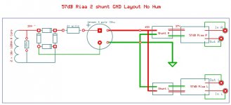
You can use that ps board if populated on only one side and using a single rectifier bridge.
Indeed, that is the best way to do it 🙂
Much better separation between channels. My new builds always use two TX. I get a larger soundstage this way.
Much better separation between channels. My new builds always use two TX. I get a larger soundstage this way.
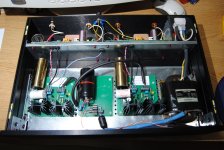
There are a few single wires passing through holes in the separation plate.One example:
You MUST run a Flow and Return PAIR through any hole.
You can run many pairs through the same hole.
NEVER run a single Flow wire, nor a single Return wire, through a metal plate hole and especially of the plate is ferrous/magnetic.
AndrewT, I don't doubt what you say, but can you explain why please?
Thanks
Lucas
P.S. Did you vote? It's gonna be one hell of a divorce if YES, don't you think? Exciting!
Thanks
Lucas
P.S. Did you vote? It's gonna be one hell of a divorce if YES, don't you think? Exciting!
Last edited:


- Home
- Source & Line
- Analogue Source
- Simplistic NJFET RIAA