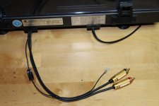
Is XLR better than phono for interconnects though?
I've never had a problem with Phono when using Neutrik phono plugs and sockets. Those cheap moulded Technics ones are terrible.
I've never had a problem with Phono when using Neutrik phono plugs and sockets. Those cheap moulded Technics ones are terrible.
I also rearranged things a bit. I turned the cablings to be the backside so now the internal signal cablings and amp-parts of boards is facing away from the poweramp. All hum is now inaudible with pot on half even with ear in cone, both channels. If i max the volume I can hear some very low hum.
Is XLR better than phono for interconnects though?
I've never had a problem with Phono when using Neutrik phono plugs and sockets. Those cheap moulded Technics ones are terrible.
I dont think so. I just hate the technical concept, they always get stuck in narrow places.
I am neither a fan of big chunky metalparts acting as antennas for the signal ground.
Playing at some 3k2 load now. Sounds great.
Last edited:
Salas,
Just got finishd putting another one together and have an unusual issue. I have one reg showing 40V the output and the other show 28V. Thought it might be a Vgs difference in Q1X, but i changed it an nothing. All lights are on and otherwise the entire circuit is working, but cannot seem to figure out how to find balance in the voltages.
Just got finishd putting another one together and have an unusual issue. I have one reg showing 40V the output and the other show 28V. Thought it might be a Vgs difference in Q1X, but i changed it an nothing. All lights are on and otherwise the entire circuit is working, but cannot seem to figure out how to find balance in the voltages.
Vdrop across R3x is tell tale of what current runs in the refs, monitor that and use proper Q3x.

Raised to around 5 k now. I dont know if there is to early days to judge and I am still not sure about what differences I hear, if any. What is that usually gets affected on different cart loads?
Perhaps problem is elsewhere, but I am inclined to doubt it. My LED ref string for the Q1 CS are within 10mV, but the voltage drop across R1x current setting resistor on two opposing channels is very different. I assumed that this CS operates independent of the circuit as a whole. If this is true, doesn't this mean that I have mismatched Vgs on Q1. Could this inequality in current draw of the two regulators affect the rail voltage or is the rail voltage simply a result of the Vref i get you spoke of above.
The LEDS will change their Vf relatively little for the position of interest as they have a stiff I/Vf curve. The main CCS current can differ a little for that including the VGS tolerances as a reason. But that is the series current source part. The Vout is a matter of the parallel or "shunt" circuit and its Vref, which is Norton I to V passive type. So the Vo depends on the current running through the trimmer and the fixed value resistor in series to it, and its directly analogous to Q3x in circuit current and its idss pre-selection. The series and parallel sections are independent and have two different jobs to do. The parallel part needs only tap on available current for its two JFET needs, the rest is shared between the output MOSFET and the load. Unless something is broken and there is a partial or full short to ground.
If R3X running current is logical (~2.5mA for 9K2 R3X), check all VGS and Vbe are reasonable too. Not only MOSFETS and JFETS but BC550C can become problematic or broken as well. After some static, soldering, probing, mishap.
I have the PSU dialed in. Having same problem as in last build. I have Jfets(369) with Appx Idss of 10.18. Rs is 2.25r(lower than recommended). Vdrop across Jfet Rs is 20mV putting Idss at about 9mA. I have 36V on the rails and I cannot get TP2 below 6.6V. I have 7.5V at the tops of the Jfets. R13 is dropping 26V
Q3x plus raising R3X on both channels to 12K. Still top side limited on my rails to about 36.5V.
I think I found it. I believe I have the bc 560 positioned incorrectly.
I think I found it. I believe I have the bc 560 positioned incorrectly.
Even with the cascode BJT stuffed correctly most builds reported here hover around 34-34.5V rail for 3.6V TP1-TP2 or 4V TP2-GND (whatever of those two checks used is valid, but TP1-TP2 is best). We have seen up to 37V depending on how some tolerances combine. So seek lower Rail+ to lower the TP2-GND reading there if still high.
Even with the cascode BJT stuffed correctly most builds reported here hover around 34-34.5V rail for 3.6V TP1-TP2
I think I was down at some 32,5ish
I think I was down at some 32,5ish
You got just one input FET in your HMC type build so its logical.
- Home
- Source & Line
- Analogue Source
- Simplistic NJFET RIAA