It will take about 10 mins for TP1-TP2 boxed up and you would not want more than 50C internal temperature in the area above the input circuitry after 30 mins in a closed box.
I design for internal worst case temperatures of 45°C or 50°C.
These are worst case design values. Big ClassA amplifiers are the exception.
I expect internal temperatures to be at least 5C below that worst case and preferably no more than 10C above room ambient.
These are worst case design values. Big ClassA amplifiers are the exception.
I expect internal temperatures to be at least 5C below that worst case and preferably no more than 10C above room ambient.
Thanks both of You. I will finish the boxing in the weekend and then start to measure the temps . drilling and measure again. Hoping to find an formula predicting the number of additional holes I will need. 🙂
Regards
Regards
It will go 40C worst case but 50C should be the max even in a heatwave in smallest bad ventilating box.
It will go 40C worst case but 50C should be the max even in a heatwave in smallest bad ventilating box.
Hi Salas,
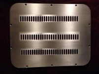
Lucky that I have friend of mine in local machine shop and I'll create more ventilation slots on my top cover. I'll send picture soon.
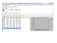
I also played with C/RC/CRC/CLC PSU simulator in order to monitor ripple effect. Please see attached pictures.
RC in my curent setup makes 1.8V ripple with Vrms equal to 48.1V
CRC is drops ripple to 33mV with Vrms equal to 49.7V.
So, does 33mV still high ripple or it is not sound noise capable level.
Attachments

Last edited:
15r seems too high.
What is your continuous current draw and what is your peak current draw?
What is your continuous current draw and what is your peak current draw?
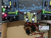
Experimenting with keantoken's Kmultiplier today. Using the probably fake SA1306 and BC550C (waiting for Sa1930 and BC337-25 to arrive). I noticed that the sound was much better when i replaced the input 330uf BG with a 1000uf Silmic. Probably 330uf was too low of a value. Output cap is a Pana FC 820uf.
Also did some tweaks on my TT. I placed a very thin layer of blu-tak in the tonearm base and used rubber grommets in the o-ring that the motor is attached. Bass is more defined now and sound is smoother.
Also did some tweaks on my TT. I placed a very thin layer of blu-tak in the tonearm base and used rubber grommets in the o-ring that the motor is attached. Bass is more defined now and sound is smoother.
Attachments
Nice. Did you feel that the Kmultiplier in the raw DC line enhanced the subjective performance evenly besides the other things you did on the TT? R.Cruz had mixed feelings about using the active filter earlier on a p2p folded for instance. What you think?
Really early to tell because i havent really done serious listening yet. I listened for about an hour in low volume so i cannot be sure. Plus i want to use the correct parts as listed by Keantoken. Im getting the parts tommorow so i'll post impressions soon
Edit: If i'll manage to repair my Esi Juli@ i'll do some vinyl ripping with and without kmultiplier and the post the files so you guys can evaluate
Edit: If i'll manage to repair my Esi Juli@ i'll do some vinyl ripping with and without kmultiplier and the post the files so you guys can evaluate
Last edited:
Hi Salas,
Lucky that I have friend of mine in local machine shop and I'll create more ventilation slots on my top cover. I'll send picture soon.
I also played with C/RC/CRC/CLC PSU simulator in order to monitor ripple effect. Please see attached pictures.
RC in my curent setup makes 1.8V ripple with Vrms equal to 48.1V
CRC is drops ripple to 33mV with Vrms equal to 49.7V.
So, does 33mV still high ripple or it is not sound noise capable level.
Use 460R as dummy load in the sim or in real life. Also 2R is larger than life ESR for the 4m7 filter cap. 0.01R maybe. RC is to just drop some Tx excessive voltage there. Further passive filtering you could apply after the output, in the remote main box even. If there is space CLC maybe is better than CRC, but bulky and costs more.
Really early to tell because i havent really done serious listening yet. I listened for about an hour in low volume so i cannot be sure. Plus i want to use the correct parts as listed by Keantoken. Im getting the parts tommorow so i'll post impressions soon
Edit: If i'll manage to repair my Esi Juli@ i'll do some vinyl ripping with and without kmultiplier and the post the files so you guys can evaluate
Alright, interesting to know. Because Kmult is compact, cheap vs quality chokes, burns very little voltage, and could be a viable alternative to those who would want to push the PSU feed quality wise.
Alright, interesting to know. Because Kmult is compact, cheap vs quality chokes, burns very little voltage, and could be a viable alternative to those who would want to push the PSU feed quality wise.
Are we discussing this one: The K Multiplier
Yep.
I see. I'm very interesting to hear the results.
I can't use CLC due to space limitations in my PSU box, but such small PCB would be no issue to integrate. So, I'm testing CRC now and if that K Multiplier will be beneficent, then yes and I'll build it. Please keep us informed about your outcome. Thank you.
Skouliki does the test.
Have you finished all other little things you wanted to do meantime?
Have you finished all other little things you wanted to do meantime?
Skouliki does the test.
Have you finished all other little things you wanted to do meantime?
Lets summarize: I'm about to finish all what I planed previously.
1. Professionally made Raw DC PCB from TB will be finished this weekend (today, I use my own). I'll add 4700uF cap at front in order to create CRC (4700uF+15R+4700uF). Bunch of 3 Watt Vishays and new MUR120 are coming Friday.
2. 47pF C2Y additions (I have about 15.150uF now) are on its way from Turkey. Shipment from Turkey is always very long. Also shipment from Russia. Some times I think that they still use horses for post office services.
3. Main Power Switch is coming from China in two days or so.
4. Top panel extra drilling (slots) will be finished by my friend this Friday.
The rest is ready and I'm about to start burn-in for about 100 hours with white nose from iPhone app.
In case that Keantoken K Multiplier will be tested and will prof its committed improvements, then I'll add it to my PSU later.
Attachments
Last edited:
This might take a bit more time. Received the SA1930 today but realized that BC337-25 was not on the order.... Also ordered some Panasonic FR's for output caps
Also ordered some Panasonic FR's for output capsReplaced the SA1306 with SA1930 but the LED in the Kmult remains lit, which probably means that FSP is drawing too much current for SA1930/BC550c combination.
- Home
- Source & Line
- Analogue Source
- Simplistic NJFET RIAA