The speakers are substantially modified ATC50s and the room is around 35m2.
The tonal balance with a Hovland Musicap is more natural and listenable. Subjectively, there is also more bass. Quality - wise, not so sure, but two SiO can really become way too bright and in your face. How the room or speakers relate to this i have no idea. After all i compare sources only.
Over the last few months i noticed that my analogue rig has been lagging far behind the digital one and this instigated my new interest in phono stages.
Maybe a more efficient and objective way to compare different phono stages would be by feeding them a signal out of an anti-riaa network. Then we could threat them as simple line stages.
About cart you mentioned the Ortofon Cadenza red. What is the TT? Having a pre with gain?
R6x is 22.3 ohms
Alright, don't you have some 100R 0.25W to parallel to the now 16.6R duo?
Alright, don't you have some 100R 0.25W to parallel to the now 16.6R duo?
Paralleled 100r to 16.6r. Value is 14.5-14.4r. Still no lights. Voltage across resistor is zero
So we went through the whole CCS circuit by now. D2X,D3X,D4X you said all light up on individual test and they have cathode on square pad, R1x you restored to typical value, Q1X is 9610 indeed, R6x is 22R indeed, Q2X can't be wrong on both channels, slim chance. This IS weird. Double check the LEDS for a last time.

OK stop for now its late. Tomorrow recheck with a clear head. Its very weird but there should be an explanation. Something with the sinks maybe. Being scratched and having scratched solder mask also? Chasing a ghost. We will find it.
I'm sure Salas will walk you through all this tomorrow, but clearly there is no current passing through R1x (else there would be voltage drop across it) nor through the LED's, hence through Q2x. I would start by isolating the LED circuit by lifting one end of R1x and R2x. If the LED's don't light then either one of the LED's is bad, or Q2x isn't conducting, or R6x is open. You already measured R6x, and we already know there is 49V at the junction of R1x and the diodes. Ergo, if the diodes are OK and R6x is OK, then the ONLY other thing is Q2x, and it is either bad (as Salas said, unlikely on both sides) or the wrong part or installed incorrectly. Either way, Q1x is not going to conduct until Q2x does.
You don't need a crimper.
A close fitting thimble over the stranded wire ends will be crimped when the screw terminal is turned down hard.
The cross-sectional area of the thimble will be bigger than the cross-sectional area of the cable. That equals lot's of air/gas between the wires.
Screw down on the thimble and the area inside the squashed oval is less than the circular cross-section. Screw down hard and the kidney shaped cross-section inside the deformed thimble is now less than the cable cross-sectional area. The wires get deformed and you end up with "gas tight" joints between the strands and between the thimble and the wires and between the thimble and the enclosing terminal.
It's the "gas tight" that gives the excellent long term electrical connection.
And a thimble replaces the need for soldered ends and is FAR BETTER than soldered ends.
I don't have any thimbles. I wish I did have a range for all my cable sizes. I would use them.
Thank you for such detailed explanation.
I'll might try that technique when my final setup will be locked.
So far, and Salas is right, I need need to test my Folded deeply in order to optimize its gain since my cartridge load vs. output is still hazy.
Gas tight copper to copper is the best connection you can get. Ericsson Telecom wire wrapped their AXE stations because wire wrapping gives a much tighter joint then solder joints. My friends still have the old tools and cable terminators. Heres https://www.youtube.com/watch?v=8SSOKppwpAE a hobbyist video. Ericsson used special tools and wire where the materials were cutting into eachother, making it completely gas tight and impossible to tear apart.
I'm going to test my Folded first time this Sunday.
My biggest concern and question is related to LEDs again....
I'm sure that my 4 LEDs (D1...4) are matched between L and R channels, but I hesitate about 7.75v setup. As you did see, I installed 2 red and 2 green LEDs and theoretically I'm getting about 8v.
When I measured these LEDs, I used 2SK117GR and 18.5V battery pack. I made it as quick test. Now I see if you leave LED longer with 9v batery and 1k5 resistor, V is slightly going up till and during 1 min time-frame is ganning from 1.89v to 1.910v. Will you recommend to re-measure that set or to try to use it as is with assumption that I might have more than 7.75v there?
One more question: do I need to connect it to TT and preamp in order to start biasing it?
I'm sure Salas will walk you through all this tomorrow, but clearly there is no current passing through R1x (else there would be voltage drop across it) nor through the LED's, hence through Q2x. I would start by isolating the LED circuit by lifting one end of R1x and R2x. If the LED's don't light then either one of the LED's is bad, or Q2x isn't conducting, or R6x is open. You already measured R6x, and we already know there is 49V at the junction of R1x and the diodes. Ergo, if the diodes are OK and R6x is OK, then the ONLY other thing is Q2x, and it is either bad (as Salas said, unlikely on both sides) or the wrong part or installed incorrectly. Either way, Q1x is not going to conduct until Q2x does.
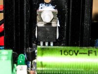
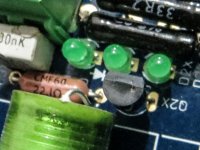
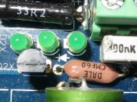
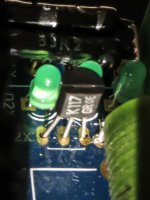
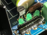
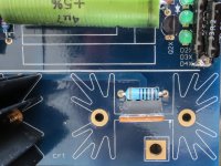
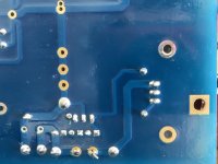
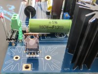
Q2x is the correct type and properly inserted.Posting some closeups for reference. Measured resistance between Drain and Source is 92-93 ohms in both channels. Going to remove heatsinks now
Attachments
I'm going to test my Folded first time this Sunday.
My biggest concern and question is related to LEDs again....
I'm sure that my 4 LEDs (D1...4) are matched between L and R channels, but I hesitate about 7.75v setup. As you did see, I installed 2 red and 2 green LEDs and theoretically I'm getting about 8v.
When I measured these LEDs, I used 2SK117GR and 18.5V battery pack. I made it as quick test. Now I see if you leave LED longer with 9v batery and 1k5 resistor, V is slightly going up till and during 1 min time-frame is ganning from 1.89v to 1.910v. Will you recommend to re-measure that set or to try to use it as is with assumption that I might have more than 7.75v there?
One more question: do I need to connect it to TT and preamp in order to start biasing it?
No need to connect to anything whilst setting bias.
Good luck.
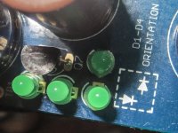
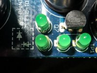
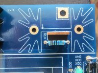
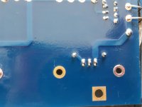
Good thing i only soldered one tab of the heatsinks, removing them was easy.
I dont see the soldermask been scratched anywhere.
Im going to re-heat the solder joints, hopefully that will solve the problem
I dont see the soldermask been scratched anywhere.
Im going to re-heat the solder joints, hopefully that will solve the problem
Attachments
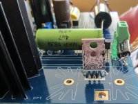
So i reheated solder joints and checked continuity up until irf9610 and everything is ok but it still doesnt work.
Im thinking i must have done something incredibly stupid in the PSU, probably the board doesnt get much current.
Im thinking i must have done something incredibly stupid in the PSU, probably the board doesnt get much current.
- Home
- Source & Line
- Analogue Source
- Simplistic NJFET RIAA