Goldfinger ! 00 Salas.
Obviously 24crt sound !
N I C E !
Thanks... I'll order the proper GR's...eBay seller screw-up !
( Ricardo, the GR's are for the BIB reg....I have 50 2SK170-BL for amp boards x4 )
Top experimenting BTW chaps !
Tally Ho !!!
Si.
PS...Ricardo, dunno if you understood...
...I can make low AND hi Ohms now...2 different resistance-wire types.
Let me know if you would like a set...
...can make & mail.
ie...4x low's & 2x highs...right ? for your build.
Also possible to make 'un-equal-sets for 'gain-matching'.
Can send some resistance wire as well...
...good 60s' stuff ( my Dad's ).
Can the folded cascode be implemented with a 28V PSU ?
By making R13 1K, R10 5.6K, R11 1.6K in your 2xK170 build. But losing 2-3dB gain AND 5V pk-pk headroom.
By making R13 1K, R10 5.6K, R11 1.6K in your 2xK170 build. But losing 2-3dB gain AND 5V pk-pk headroom.
Thank you I have a "normal" simplistic, 48dB running at 28V that needs some work than !!!
You should watch it ain't overloading with a given cart if you will convert it. 28V B+ is rather little.
I am using a 30VAC TX, so I have 42VDC before the shunts.
Maybe I could stretch shunts output to 32V....
Maybe I could stretch shunts output to 32V....
That would take R13 1.2K 1W, R10 6K (12K//12K?), R11 1.5K for 57.4dB and better headroom.
Perfect for a chrstmas present... thank you again Salas

Hi Peoples
Strange...
...just measured my 47n & 15n Ruskie K72's again today...
...and with same meter, same temp & same desk, leads & cup of coffee next to meter...
...they don't seem to 'drift' as before !
Today, they appear WAY more stable !
( must be thawing-out from Siberian cold-storage ! )
-------
Bit of advice please Gentlemen !
Miller/stray capacitance & RIAA values.
OK...got the 'official figures' 47k, 6.8k, 47n, 15.5n.
I guess some allowance for Miller/stray capacitance has been made here.
Just asking...
...as have been using a typical 'on-line RIAA calculator' ( mh-audio.nl )...
...to see if I can 'slightly tweek' the values to better match & suit the C's & R's I have to use.
On entering...47k I get...6834r, 15.95n & 46.52n
Just playing with the combinations really.
I had always thought to use 'fixed resistors', & adjust using 'small caps'...
...but...
...If I shift the 47k down a tad, to about 45.3k...both my cap values 'sync'...
...which could be good.
Just need a 45.3k resistor, which is no problem, I think.
Question is...
...what amount of Miller/stray capacitance, should I be factoring in to this calc. ?
I am def. a subjectivist with sound...
...perhaps it will need some adjustment later...
...but a good 'calced' value to start with, would be helpfull.
Not trying to change 'massively' from 'official values'...
...just trying to get best parts match etc...
...and possibly avoid buying more caps to try.
Will try a few different ones, I'm sure...
...a good match between the 2 R's & 2 C's, will help.
---------
JFET testing went OK...
...I think a good range to match position/channel from...
...slightly low, on average, for BL's...
...but majority, within the same 'low BL range'.
Good news ! ( I think )
Cheers.
Si.
( actualy turned the iron on today !!!...NOT eBay !!! )
Carefull.... Riaa values depend on input stage output impedance, output stage iput impedance and second stage miller.
Carefull.... Riaa values depend on input stage output impedance, output stage input impedance and second stage miller.
So:
a) How does one know how much 2nd stage Miller capacitance there is?
Can we measure it with a capacitance meter? (In which case, where do we put the leads?)
and
b) How does X pF of Miller capacitance affect the value of the RIAA cap(s)?
Thanks,
Andy
Hi Ricardo
Yep...
...this is the question...Miller...how much ?
I think a possible shift from 47k to say 45.3k...should be pretty minimal...
...as long as other values are 'tweeked' accordingly.
That's the general plan, anyhow.
How much Miller on 'official values' ?
Any idea ?
Cheers.
Si.
Yep...
...this is the question...Miller...how much ?
I think a possible shift from 47k to say 45.3k...should be pretty minimal...
...as long as other values are 'tweeked' accordingly.
That's the general plan, anyhow.
How much Miller on 'official values' ?
Any idea ?
Cheers.
Si.
Basically...
...my K72's are 'slightly HIGH' @ 48.2, 48.2, 48.3, 48.3
( also have ones @ 47.1, 47.9, 48.0, 48.6 )
Si.
...my K72's are 'slightly HIGH' @ 48.2, 48.2, 48.3, 48.3
( also have ones @ 47.1, 47.9, 48.0, 48.6 )
Si.
Avoid Riaa calculators, follow the recommended values. There are combined source impedance and Miller contributions in each version. Miller varies with gain and source degeneration in both stages in each version. Even cascoding in first stage just reduces it, it does not eliminate it. Mathematics about Miller capacitance or "effect" are easy to find if you will google it up.
Hi Nick ,compliment for the new folded RIIA! Apart the use of K369 and the trimmer ,I noted the presence of an active polarisation of the output buffer. I like very much to use CCS in the audio circuits, cause always they give to music more air and dynamic impact...in few words, the music breath! I've the old MC version, V1102FO, in balanced mode , and I modified it with the CCS. I measured the voltage across the reristor (1K5) that polarize the
buffer (K170), resulting about 12V. With the Ohm's Law I compute the current that flows across the resistor (12V/1500R= 0.008A = 8mA). I had some K170 with exactly this Idss and I swapped the resistor with the JFET. Very simple job, but amazing! Very reccomanded to all the owners of the old version.
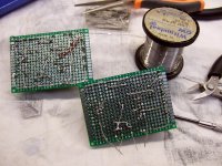
P.S. Can you post also the photo of the soldering side of the folded version? I think this is very useful, for all us, to understand how lay out the single components and the rails.
buffer (K170), resulting about 12V. With the Ohm's Law I compute the current that flows across the resistor (12V/1500R= 0.008A = 8mA). I had some K170 with exactly this Idss and I swapped the resistor with the JFET. Very simple job, but amazing! Very reccomanded to all the owners of the old version.
P.S. Can you post also the photo of the soldering side of the folded version? I think this is very useful, for all us, to understand how lay out the single components and the rails.
Salas,
Do you recommend a prefilter? Using dual SSLV1.1
Its good to break some EMI from the rectification. So drop 1 or 2 volts with an R before board's main C if with outboard bridge or by a small hack. Better still is choke input with some leftover speaker air coil.
- Home
- Source & Line
- Analogue Source
- Simplistic NJFET RIAA