Now it fully works. There should be signal. Only thing to keep in mind changing, is that with 7.7mA q2 the d to gnd being ~13V biases q5 over 7.7mA pushing it. Its either you lower R6 until you get ~10V across R7, or you use q2 8.5mA, or you just use a 10mA q5 to take the bias easy, and you use the now 7.7mA q5 as matched q2 for the other channel. I would prefer ~8.5mA q2 as a solution so to preserve the target gain and thd also. Well done up to now.
Thanks for your help Salas, I'm not getting a signal right now, but am just using a little MP3 player with the volume set to -50db to test. I'll have another look at it tomorrow.
In a sort of related matter, I've just ordered one of these (DIY version):
audio mods Rega arm conversion kits and DIY mods
They look amazing, I'm currently using a modded Rb251 on my DIY Lenco L75. The reviews are fantastic as well.
In a sort of related matter, I've just ordered one of these (DIY version):
audio mods Rega arm conversion kits and DIY mods
They look amazing, I'm currently using a modded Rb251 on my DIY Lenco L75. The reviews are fantastic as well.
Nice arm gear. You would need 1kHz wav and LPAD attenuator maybe 1:1000 10k series, 10R across inside a male RCA. Let the PC play the wav, measure 500mV on attenuator cable input mini jack, should give 0.5mV on the other end, and you must measure around 500mV on phono out. A DVM in ACV must catch that. That way you can check the final channels are near too.
OK, I have output, but much too low gain.
A quick test using the tone generator my Nakamichi, 1.08mV input @ 400Hz gives around 5.5mV output.
I know 400Hz will give a different result due to RIAA eq, but its around 200x to low at the minute...
A quick test using the tone generator my Nakamichi, 1.08mV input @ 400Hz gives around 5.5mV output.
I know 400Hz will give a different result due to RIAA eq, but its around 200x to low at the minute...
Maybe there is still something not connected properly in there we have to catch. Also the output impedance of your Nak if its high enough could be dividing with the low input load resistor.
R11 drops 32V
Too much. Should be made to be around 25V. Too much bias in the output fet. Is R7 1.5k?
Too much. Should be made to be around 25V. Too much bias in the output fet. Is R7 1.5k?
Yes it is 1.5k
If R7 drops 12.8V as you posted, then 8.53mA is indicated. That should come through R11. That would drop ~33V, so the 32V you measured computes. Works, but you got to do something to give Q5 more VDS voltage to breathe. Its the problem with the 7.7mA q2 giving high VDS I described. There are several ways, best is to use a higher IDSS q2 as original on schematic. If you wanna do a fast check, find a resistor to parallel R11 for a total of ~2.7k and check for healthier signal. Later you can optimize.
hi salas, this thread is 675 pages long so i guess it's a strong indication that there are plenty of interest with regards to this project. just wondering if a GB for a simplistic NJFET RIAA pcb is possible/feasible?
Q2 is now 8.8mA, q5 is 8.2mA
r7 now drop 9.7v, r10 drops 25.5v, r11 drops 35V
which means q5 is biased at 6.4mA, correct?
r7 now drop 9.7v, r10 drops 25.5v, r11 drops 35V
which means q5 is biased at 6.4mA, correct?
hi salas, this thread is 675 pages long so i guess it's a strong indication that there are plenty of interest with regards to this project. just wondering if a GB for a simplistic NJFET RIAA pcb is possible/feasible?
No. Its not an easy project to lend itself to such spreading. The pdf instructions is already a long shot.
Q2 is now 8.8mA, q5 is 8.2mA
r7 now drop 9.7v, r10 drops 25.5v, r11 drops 35V
which means q5 is biased at 6.4mA, correct?
If r11 drops 25V that is. Maybe you wrote the drops on r10,r11 vice versa?
(hopefully) almost there now.
I've built the second (Left) channel. Measurements are:
Left Right
LEDs 7.11 7.07
Gate on Inputs 6.47 6.44
Gate on Q2 9.25 9.80
Gate on Q5 20.1 20.6
Perhaps I need to change one of my input Jfets on the left channel for slightly lower/higher idss?
Hum is reasonbly bad on the left channel and very bad on the right, with no input wires even connected.
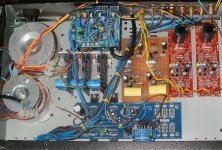
I haven't mesured the gain yet, I will do that when I have sorted my hum problems. The shunt regs have been adjusted to give excatly 45V after 10 minutes. I'm only running the shunts with 33R R1 at the minute so they maybe aren't as quiet as they can be, but should still be quiet enough.
The phono stage is next to the shunts, I've tried moving the board around when powered to listen if the hum changes, it doesn't, so it doesn't appear to be interference.
Here is a picture, all of the high-level signal and power supply ground wires go back to a star point on the back panel. When I connect the signal wires the grounds will come straight to the phono board.
PS there is insulation under the phono board to insulate it from the case 🙂
I've built the second (Left) channel. Measurements are:
Left Right
LEDs 7.11 7.07
Gate on Inputs 6.47 6.44
Gate on Q2 9.25 9.80
Gate on Q5 20.1 20.6
Perhaps I need to change one of my input Jfets on the left channel for slightly lower/higher idss?
Hum is reasonbly bad on the left channel and very bad on the right, with no input wires even connected.
I haven't mesured the gain yet, I will do that when I have sorted my hum problems. The shunt regs have been adjusted to give excatly 45V after 10 minutes. I'm only running the shunts with 33R R1 at the minute so they maybe aren't as quiet as they can be, but should still be quiet enough.
The phono stage is next to the shunts, I've tried moving the board around when powered to listen if the hum changes, it doesn't, so it doesn't appear to be interference.
Here is a picture, all of the high-level signal and power supply ground wires go back to a star point on the back panel. When I connect the signal wires the grounds will come straight to the phono board.
PS there is insulation under the phono board to insulate it from the case 🙂
Attachments
Last edited:
Please tell me drain to ground voltages, not gate, and I will reply if OK.
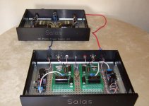
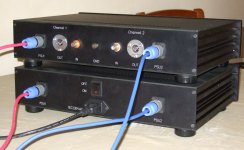
You did a lot of work, but unfortunately a 60dB gain unshielded phono can not afford two toroidal transformers in the same box for hum. The solution will be its own box, just phono. DC only will come in, and all signal cabling will be shielded. Trafo and raw dc rectification, main capacitors, in a psu box, away, connecting with a umbilical.
You did a lot of work, but unfortunately a 60dB gain unshielded phono can not afford two toroidal transformers in the same box for hum. The solution will be its own box, just phono. DC only will come in, and all signal cabling will be shielded. Trafo and raw dc rectification, main capacitors, in a psu box, away, connecting with a umbilical.
Sorry Salas, they are definitely drain voltages, not gate.
There are actually three in the case, a 30VA, a 60Va and a ~100VA (this is for the phono)
I was fearing you'd say that, I would like to keep it in one box if at all possible (and left the possibility of adding shielding in the case if it were needed). I have a few things I will try (I think the 30VA toroid for the DC-B1 is the noisiest, I could have everything but the phono regs powered from the 60VA toroid)
What tweaks do I need to make to optimise the voltages please?
Your drain voltages are very good. You will only need to change something if your levels between channel outputs will have gross differences. By using a trimmer instead of R6 you can match q2 drains dc or tweak gain and thd since its changing local degeneration. As for having no hum and keeping the thing in there, I am sorry, many tried before but no cigar. It would only live well with Rcore and every AC cable tacked away to the other corner in a fairly wide box. Still not as good as a two box build as in the pics attached, for no AC wiring entering. Many examples here before even with with FFT showing harmonic noise with different box and arrangement steps etc. In your shoes, I would get a small extra box, put the phono boards inside it ONLY, and run the 4 wire reg outputs to it from your now box. Thankfully the regs can save a lot of loss with 4 wire config when away from their client boards. Looks like the cheapest and lowest box count solution. The box must be connected to 0 PSU, and audio signal cabling be shielded coax. Nice up to now non the less, congrats.
Attachments
Thats impressive Salas, very nice.
In my build it is a case of 1 step forward, 2 back. I can't get any sound out of the Left channel. All my drains measure OK (input 6.47, Q2 9.50, Q5 20.2. CBE of BC550 is 11.1/7.10/6.47V)
The top of C3 is at 7.1V on my non-working channel and 12V on the working channel.
I have replaced the BC550 on the non-working board, and removed and re-measured the input JFets and also replaced Q6. Any ideas please?
One again, thanks for your help.
The good news is that the right channel sounds very promising. Hum is reasonably low-level now, definitely something I might be able to manage. Sound quality is very good. My case isn't earthed yet and I will try adding sheilding around the transformers.
Do you still have the high IDSS that troubled you initially in the two input fets in the ''wrong'' board, for instance? You went ~7.7 for those and changed 550, finding the collector comfortably above 10V. That collector voltage must reflect all the way up to the inter-stage coupling capacitor.
Since you got one good channel now, life can be easier, if its a wrong connection even. You can put the 2 boards under inspection for continuity of connections and trace out the bad against the good.
Since you got one good channel now, life can be easier, if its a wrong connection even. You can put the 2 boards under inspection for continuity of connections and trace out the bad against the good.
- Home
- Source & Line
- Analogue Source
- Simplistic NJFET RIAA