Standing 1118mm tall its challenging to fit in a standard post envelope 😀
this is the height including the tweeters?
did you by design choose compression for your speakers chassis?
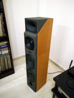
Yes that's the top to floor distance, its a tall enough double cabinet speaker.
Wow beautiful speakers! Is the sub section simply ported out the front or horn areangement? (I only just started looking up speaker construction yesterday lol)
More details please 🙂
Sorry to derail this thread.
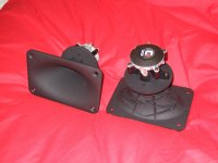
Its simply bass reflex. The horns & compression drivers inside the top cabinet look like this:
Very nice - do you use passive cross over circuit in the speaker?
I’m now considering just making some subs initially to supplement my LS50s (they are a bit light on the low end) - barely finished my phono and already looking for the next project 😛
Wow. These are very nice looking speakers and based that you made these, I’m sure they are sound amazingly well. You are already repeated Dr. Pavlov dogs salivation experiment on us. I’ll be your follower if you will decide to open new thread for you speakers design DYI. In serious note, room’s acoustic is not that easy subject (someone wrote that acoustic design is a hundreds compromises and equation with infinity amount of variables) and all of us might get different results, but any way it is make sense to try.
Very nice - do you use passive cross over circuit in the speaker?
I’m now considering just making some subs initially to supplement my LS50s (they are a bit light on the low end) - barely finished my phono and already looking for the next project 😛
Yes its a passively crossed conventional speaker.
Hi Salas I sent you a message re speakers so I can avoid detailing this thread further - not sure if your inbox is full ><
Hi Salas,
did you ever build the SimplisticFoldedPhono with changeable gain so that
one can switch between MM/MC/HoMC/LoMC ?
Greetings
Ulf
did you ever build the SimplisticFoldedPhono with changeable gain so that
one can switch between MM/MC/HoMC/LoMC ?
Greetings
Ulf
I built it for MM or MC part values as listed in the guide but not with switches. A Greek guy in a local forum built it with female pin headers for each differentiating component to can simply change them without desoldering for another cartridge type in the future and it works without noises (for now). Fortunately its about rather few components to change its sensitivity version.
I've build mine too, with female pins, for MM and Low MC, no problem if done properly.
First solution I thought: small diy pcb on top of the pcb attached the pin headers for quick swap
Second solution: buying two boards from Tea-Bag and stuffing the second one with only the gain section (no simplistic psu, no RIAA). It will be attached to the first one with two relays, one before the setting resistor (R12+trimmer) and the other before RIAA cap (C3). This way you don't have to buy another set of signal caps (4 of them), big pros for those with expensive caps
Third solution: buy two sets of Folded phonos. Very useful for the people with two turntables
What do you think of the second solution Salas ?
After having the phono for so long and going toe to toe with a much much more expensive commercial one, I consider this as the weakest point.
Last edited:
I think that's a good solution conceptually speaking but it remains to be proved if it will be sensitive to noise or not because of the relays and wiring between two boards.
If done properly, it's a minimum wiring solution, 1 cm for the header to connect to the second board (upside down). Forgot another relay at the input. This relay and the one at the input of RIAA are the most critical and should use minimal wiring, millimeters if possible.I think that's a good solution architecturally speaking but it remains to be proved if it will be sensitive to noise or not because of the relays and wiring between two boards.
One minor downside is that you'll have to wait for the warm up period for each gain section. Using another simplistic psu will bring up more heat.
For such small signal does the normal relay type (say the one from I-Select) qualify ?
Good morning,
sorry für being off topic, but instead of building the folded version for MM
what about buiding your "valve itch" Phono for MM ? Can you describe the
sonically difference between the folded an the valve itch? Is there one device
you´d prefere?
Greetings
ulf
sorry für being off topic, but instead of building the folded version for MM
what about buiding your "valve itch" Phono for MM ? Can you describe the
sonically difference between the folded an the valve itch? Is there one device
you´d prefere?
Greetings
ulf
The Valve Itch is a good option if looking for original vacuum triode sound qualities, has meatier impact across the range, but this one has more resolution due to lower intrinsic noise floor and much higher transconductance while being smooth. Also follows a classic architecture like most valve phonos do. Block by block with passive RIAA and no loop feedback. JFETs are like solid state pentodes save the heaters. So there is more consistency between the two phonos than one might initially think.
- Home
- Source & Line
- Analogue Source
- Simplistic NJFET RIAA