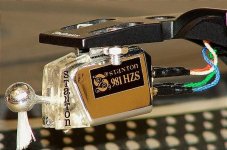
Another succesful trial - the Stanton 981LZS with D-98S and D-98 mkIIS stylii works just wonderfully with the 63dB FSP and CL Satisfy arm! Just wonderful!
Regards
Is it a very low output MM like 0.2mV-0.3mV at 5cm/sec?
Small sinks for 10R R1. They used larger ones or the floor of bigger boxes for that version. Use 15R later.
Salas,
What's "better", Bigger sinks or a 15R resistor in place of 10R? I am thinking bigger sinks would be potentially better sounding.
I can do either, or both. I don't have the parts on hand so I would have to order all the parts anyways. At this point it might be easier just to install a taller sink, Probably a 54mm tall sink instead of the 38mm tall sink I have now.
Also, I adjusted the shunt a little, settled at 27.1 and 27.2V rails to get 3.6V at the phono stage Vgs Q1. It sounds superb now. Really good. Much more liquid and dynamic than the batteries. It sounds totally linear and smooth.
Start with 54mm sinks. But keep a couple of 15R low ppm 2W in hand. In your situation using a single input JFET with high value source resistor, its bias drift tendency with ambient temp is very much reduced. So use a criterion of no more than 50C average internal air temperature with a ventilated lid put on (drill few holes under and over each sink's vicinity). You maybe have a K thermocouple wire or kitchen probe to monitor that. Allow for summer room temp usual rise in your location. Good you had tangible subjective improvements. It took you enough precise work to make those nicely populated matrix board regs.
1377 Pages!
Can someone tell me where is the last version of the circuit, supply etc.?
There are links in post #1. Bottom link is newest version. There is pdf guide in all versions.
Is it a very low output MM like 0.2mV-0.3mV at 5cm/sec?
Yepp.
I remember that cart, never listened to it though. It was Stanton's best they used to say in the press. Behaving like an MC that you could exchange its stylus kinda.
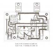
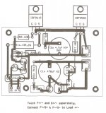
My own pcb for the FSP regulated supply
I have bought the latest pcb for this project but I would still like build my own MM version. I know it may not make sense to some but I'd like to make my own prototype.
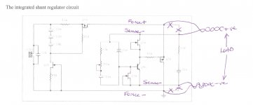
My question is about the Force and Sense circuits in the regulated power supply. I attach 2 scans: one of how I interpret the F & S circuits and the other is my circuit design. I hope both easily legible.
Can someone who has built his own pcbs comment on my attempt?
I have bought the latest pcb for this project but I would still like build my own MM version. I know it may not make sense to some but I'd like to make my own prototype.
My question is about the Force and Sense circuits in the regulated power supply. I attach 2 scans: one of how I interpret the F & S circuits and the other is my circuit design. I hope both easily legible.
Can someone who has built his own pcbs comment on my attempt?
Attachments
I have bought the latest pcb for this project but I would still like build my own MM version. I know it may not make sense to some but I'd like to make my own prototype.
My question is about the Force and Sense circuits in the regulated power supply. I attach 2 scans: one of how I interpret the F & S circuits and the other is my circuit design. I hope both easily legible.
Can someone who has built his own pcbs comment on my attempt?
You separated them alright. Better use R5x C2x as part of the "force" section. The FSP board does use sense and force separately despite the conceptual schematic BTW.
I think the two force wires should be twisted as a pair. They are the flow and return of the main power feed currents.I have bought the latest pcb for this project but I would still like build my own MM version. I know it may not make sense to some but I'd like to make my own prototype.
My question is about the Force and Sense circuits in the regulated power supply. I attach 2 scans: one of how I interpret the F & S circuits and the other is my circuit design. I hope both easily legible.
Can someone who has built his own pcbs comment on my attempt?
The two sense wires should be another twisted pair. Again flow and return of the sense circuit currents.
In addition the sense circuit with it's extended wiring needs maximum attenuation of interference confusing the measurement of the voltage errors at the load.
The PCB should also maintain these pairs (for traces passing the same currents) to minimise the effects of interference.
Thanks Salas and AndrewT for your advice and suggestions.
I have redrawn my pcb layout as per Salas advice and would like you to have a look to make sure I understood correctly. I have a couple cylindrical MKPs which I'll mount vertically.
When I made a similar HV Regulator (again by Salas - thanks!) I didn't have much luck. But then, luckily a DIYA board was made available. I don't wish to go the same route!
Thanks in advance and all the best for the festive season to all DIYA members
Attachments
I remember that cart, never listened to it though. It was Stanton's best they used to say in the press. Behaving like an MC that you could exchange its stylus kinda.
They actually made one to even better specs - not sure of if I'll go for that one - the WOS-100 something.
I believe its an selected 981 HZS. I've sampled this direction as far as I'm wiling to go and have som truly amazing carts to put in the drawer - to enjoy at times... So the Stanton/Picering paths carts and needles are in the safe now.
Regards
Last edited:
- Home
- Source & Line
- Analogue Source
- Simplistic NJFET RIAA