No its not a technical restriction its just for dual mono. Dual secondaries work too.Is there any technical reason why we need 2 transformers for the power supply?
Or is it just for a dual mono power supply?
Is it ok to use one 60VA 2x 36V secondary transformer?
@Salas:
I did try the active filter schematics you introduced in your post (#12564). It works very well and make me wonder if actual results could be upgraded. My suggestions about actual schematics, please:
(i) Darlington transistor replacing (Qmult) (BD139), would upgrade actual filter performance?
(ii) MOS transistor could be a better alternative, in your opinion, please?
Thank you very much!
Sincerely yours,
Ion
Double PSRR will be with two same ones in series if you can afford the 3V loss. You will not need the 100uF in between. Alternatives in the single cell will not reach such good PSRR.
Double PSRR will be with two same ones in series if you can afford the 3V loss. You will not need the 100uF in between. Alternatives in the single cell will not reach such good PSRR.
What is the minimum so one can se if the losses are to big? 😉
Regards
I don't know where he tested it and how much headroom he got for his app, I just remind the loss factor. In FSP as long as we got 10V dif between DCin connector to rail+ reg out, its a nice margin both for stability, heat, mains play, and parasitic Mosfet capacitance.
I don't know where he tested it and how much headroom he got for his app, I just remind the loss factor. In FSP as long as we got 10V dif between DCin connector to rail+ reg out, its a nice margin both for stability, heat, mains play, and parasitic Mosfet capacitance.
Yes that is one way to explain it. I believe it was late last year there was a lot of discussion about trafos and as I recall (I might be wrong) there was a minimum DC one should be above. That would be another way to answer the same question.
Regards
hi Salas.
today I resumed work.
no effect with 2 potmeter 100 Ohm.
I will try now with the potmeter 1 k.
positive note: I retrieved a power supply from other work(not finished)that provides 29 volt.
on the collector of the Bc560c I will always measure 3.4 volts?
thanks in advance.
today I resumed work.
no effect with 2 potmeter 100 Ohm.
I will try now with the potmeter 1 k.
positive note: I retrieved a power supply from other work(not finished)that provides 29 volt.
on the collector of the Bc560c I will always measure 3.4 volts?
thanks in advance.
In respect to ground I mean, don't look how builders bias a normal FSP, your build is individual. Even if you had not good IDSS match on the input 2SK170BL, with 29V and 1K trimmer you should have margin to match collector voltages in the channels.
been experimenting with a c multiplier feeding the shunts and although I notice an improvement in the bass that seems cleaner, there is a muffling effect in the mids and highs. The typical wide soundstage of the folded shrinks .... I would say the magic is gone...
I know my build I used for this test is very well tuned as is, so this add-on would need further care to come alive ....
I know that in the folded everything counts (even a change in the raw psu caps is quite noticeable - once I used two 15000u Jensen in parallel and also lost the magic so I reverted to using a single cap).
Anyway, I measured 300mv ripple into the cap multiplier and 0.8mV in the output so it really cleans but even without this circuit the shunt output is completely ripple free (I could not read anything clearly with my setup) so I believe the shunt PSRR is exceptional and does not need any "help".
Please bear in mind that I only did this experiment for learning purposes and not because I was trying to improve a flaw in the folded.
The other guys that had only positive results maybe had different levels of EMI/RFI pollution to fight. You can even try the simpler filter with single BD139 (quan, bucurb), has different impedance.
Because there will always be various needs and evaluations in different systems that is why I avoided to design anything more than a generic supply in the guide without passive or active filtering extras which I tested the prototype with to secure a minimum correct working order and sound quality. More is up to the builders creativity, installation needs, and subjective preferences.
Because there will always be various needs and evaluations in different systems that is why I avoided to design anything more than a generic supply in the guide without passive or active filtering extras which I tested the prototype with to secure a minimum correct working order and sound quality. More is up to the builders creativity, installation needs, and subjective preferences.
Dyna 10x4 mkII vs Denon DL110
After several days of listening the Dynavector 10x4 mkII i installed back my trusty Denon DL110. Listening impressions were done with the same loading resistor (5k).
The Dyna is a better cartridge in all aspects. The sound stage has a greater sense of 3d depth compared to the Denon which sounds a bit more flat. Stereo image of dyna is focused on the "center", Denon's image is kind of streched to the sides. Midrange and treble sound sweeter with Dyna, Denon sounds a bit "dry" in comparison. Inner groove distortion is more apparent with Denon, Dyna is much better in that aspect.
The musicality of Dyna is also much better. The music has a nice "flow". It was easier for me to stop listening to the recording and just enjoy music.
10x4 is a great sounding cart which im probably going to upgrade to when i can afford it. I must also admit that DL110 still offers incredible value for money.
Thanks again to Salas for providing me the cart .
Attachments
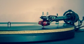
Since I had it, why not lend it for a fresh comparison. The above is nice info between two popular HMC models many are eying to combine with FSP. Current model 10X5 can only be bit better than the 10X4 MKII if anything. Thanks for your contribution. 
I am not surprised by your experience
Seems to me a more benign approach to a little more energy storage would be to add an LC filter after the rectifier board.
I have a pair of .15 H - 7R choke that I want to try after I (finally) get the thing running. I hope to be able to place these chokes in the box with the phono amp. I know they will fit but will they interfere?
Using the DUNCAN AMPS PS tool shows a massive reduction in ripple. I figure a shunt reg does not mind having less work to do as opposed to Brian Lowe's serial reg which he says prefers having a rawer input.
My modelling uses an output cap of 1400uF. Nothing changes much going higher or lower.
All conjecture at this point.
Will report.
been experimenting with a c multiplier feeding the shunts and although I notice an improvement in the bass that seems cleaner, there is a muffling effect in the mids and highs. The typical wide soundstage of the folded shrinks .... I would say the magic is gone...
I know my build I used for this test is very well tuned as is, so this add-on would need further care to come alive ....
I know that in the folded everything counts (even a change in the raw psu caps is quite noticeable - once I used two 15000u Jensen in parallel and also lost the magic so I reverted to using a single cap).
Anyway, I measured 300mv ripple into the cap multiplier and 0.8mV in the output so it really cleans but even without this circuit the shunt output is completely ripple free (I could not read anything clearly with my setup) so I believe the shunt PSRR is exceptional and does not need any "help".
Please bear in mind that I only did this experiment for learning purposes and not because I was trying to improve a flaw in the folded.
Seems to me a more benign approach to a little more energy storage would be to add an LC filter after the rectifier board.
I have a pair of .15 H - 7R choke that I want to try after I (finally) get the thing running. I hope to be able to place these chokes in the box with the phono amp. I know they will fit but will they interfere?
Using the DUNCAN AMPS PS tool shows a massive reduction in ripple. I figure a shunt reg does not mind having less work to do as opposed to Brian Lowe's serial reg which he says prefers having a rawer input.
My modelling uses an output cap of 1400uF. Nothing changes much going higher or lower.
All conjecture at this point.
Will report.
PSUs and boards ready.
I just tested the PSUs, I got 44,2V
I wanted to know what should be the position of VR1 and VR2X before plugging the board for biasing?
I just tested the PSUs, I got 44,2V
I wanted to know what should be the position of VR1 and VR2X before plugging the board for biasing?
Salas. I know that early on, Rush used the RIAA feeding directly into the DCB1 and that there was a questiion of proper grounding. I have something similar planned for a friend. I was going to feed the RIAA output to a high Zin buffer, allowing a much lower value cap on the output. This biffer will feed a DCB1 buffer so that he can have a passive volume control. I plan to include all this in the same box, minus the tranformer and prereg. I haev a transformer that i can use to power the buffers with independently, but I also could pull off the same transformers used for the RIAA(they are CT) and each channel would have one transformer for the entire channel, only having two different PSU's. In your opinion, which is the better scenario?
- Home
- Source & Line
- Analogue Source
- Simplistic NJFET RIAA