At that case, I need to dis-solder my Nichicons KGs. I'll do that over this weekend.
In addition, I gave you just an example of that type of through-whole small chokes that I can use in your Raw DC PCB (Just got that from Tea Bag). You might find other through-whole "mini" chokes from Mouser or Digikey production stock that will be more sustainable there on PCB. That will be a solution for me, since I can't use DC reactor 200mA choke. No space in my box. Thank you.
You don't have to desolder them, ESR can be measured in circuit. The test signal is going to go small due to very low value Ohmic load. I need those figures to see if there will be any peak with that small inductance or not.
Hi Salas,
Please see attached picture and let me know if I got you right.
..................
The schema is not right...................... The schema is alright. The noted slow blow fuse rating varies according to your specific transformer(s) primary fusing spec of course.
There is a 1r0 in both Fault Current routes that is not bypassed with the inverse parallel high power diodes.
The reason we have to connect the isolated metal back to PE is so that Fault current can pass and blow the fuse very quickly.
Adding resistance to that route defeats the safety purpose of the metal to PE link.
They are there to keep the two channels return paths separate loop. If there is concern of passing really big currents they can be replaced with jumpers so there is nothing possible to break in the fault path before a fuse. That would ask for a hefty bridge instead of 3A to 5A diodes also. Safe if someone will go to say 300VA Tx.
You don't have to desolder them, ESR can be measured in circuit. The test signal is going to go small due to very low value Ohmic load. I need those figures to see if there will be any peak with that small inductance or not.
OK. I'll measure both caps tomorrow.
So, the schema is OK. Right?
Again, and since I use Tea Bag's PSU PCB, I have no way to add CRC or CLC into it.
There is a palce for R there prior big Lytic C (4700uF) in order to create RC filter.
So, I can manipulate with that R value or to install RF through-hole choke.
For R we clear and in my case I need 15R 2+Watt there (lets say CPF315R000FKE14).
For RF choke (instead of R) is still needed to provide measurements to Salas. Am I Right?
Last edited:
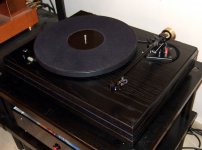
The now mutant other TT is coming home today so I hope all operations went well. 33/45 buttons added even. 😉
Are you shure Alex that this is the right picture?
Salas, would it be any gain in buying a heftier trans and follow this CRC to get it down?
Regards
For Turbon: That picture was taken from original FS manual and 15R is added prior C 4700uF to maintain RC filter. No any other changes were made to the original schematic.
Some pics?
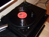
Listened to few tracks only as it came back home just an hour ago. But here you are, fast photo break 4U:
Attachments
OK. I'll measure both caps tomorrow.
So, the schema is OK. Right?
Again, and since I use Tea Bag's PSU PCB, I have no way to add CRC or CLC into it.
There is a palce for R there prior big Lytic C (4700uF) in order to create RC filter.
So, I can manipulate with that R value or to install RF through-hole choke.
For R we clear and in my case I need 15R 2+Watt there (lets say CPF315R000FKE14).
For RF choke (instead of R) is still needed to provide measurements to Salas. Am I Right?
The schema is the original, yes.
That 15R should be 2W to 5W. Better 3W-5W. That Vishay # very good.

RF choke might create resonance peak, let me know ESR results so to sim first.
The 774 is a medium mass arm now, wand stuffed with 6.5g silicone, also got a coax gold hue brass counterweight addition. The Cardas wiring got its grounding scheme reworked. The CJ58 deck has mutated to a DC motor TT now with double decoupled aluminum motor base, plexiglass plinth base, Corian feet, balance weight across the arm at the sub-chassis for the springs to float better, it feels two times heavier as a unit after those things. Even got 33/45 speed controls. Thanks to my expert friend Mike.
The one with the Dyna 10x HOMC is going to play through the Itch to bypass SUT influence and I will remeasure/ponder on the valve unit, if I extract more performance I will let you know Mr. Mago some time later in the VI thread. Now the mutant TT on FS phono plays perfect pitch and resolution is way up so I will have fun for a while before thinking Itch revisited scrutiny.🙂
Finally got my Mcap SOILs and charcroft Zs for R1/14 and riaa. Weekend is saved 😀...
Regards
Regards
What sort of DC motor installed?
Pull out from an old made in Korea TT. Along with its control and servo electronics. Works fine. Has a faded marking at the motor's back that reminds the Mitsubishi logo.
Finally got my Mcap SOILs and charcroft Zs for R1/14 and riaa. Weekend is saved 😀...
Regards
- Home
- Source & Line
- Analogue Source
- Simplistic NJFET RIAA