I also want to extend to Salas my thanks for sharing this project. I've been lurking on this thread for quite a while now, and am definitely planning on implementing this phono stage.
Great work!
Terry
Great work!
Terry
Soon I will join the "experienced" ones 😉
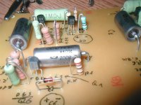
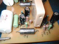
All resistors in place (had to deviate a little from Lee´s layout to acomodate the uge 1M kiwame).
Promising.....
Just a little question.. I know my version has a buffered output and my intention is to do the following path:
Riaa -> 50k dual log pot -> Pedja Buffer -> Meridian 103 power amp.
Is this a good idea ? I just want to avoid the 101b opamp output stage but I am a bit confused....
Regards
Ricardo
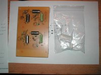
Attachments
The Pedja has a better chance of sounding more transparent than the 101b I guess. But you just have to compare. Maybe you will need 101's gain. I would set up phono-101-103 first. After all has burned in, and familiar with, I would listen VS phono-pot-Pedja-103.
Go Ricardo, Go! 
Got the k40y-9 PIO russian caps today, in the .15u value. They're burning in 😀
Got the k40y-9 PIO russian caps today, in the .15u value. They're burning in 😀
metalman said:I also want to extend to Salas my thanks for sharing this project. I've been lurking on this thread for quite a while now, and am definitely planning on implementing this phono stage.
Great work!
Terry
Thank you for your kind words. Good luck with your planned build. We will be happy to know your experiences and tunings when ready. What is your TT, arm, cart and rest of system right now? Already having a phono? DIY?
salas said:The Pedja has a better chance of sounding more transparent than the 101b I guess. But you just have to compare. Maybe you will need 101's gain. I would set up phono-101-103 first. After all has burned in, and familiar with, I would listen VS phono-pot-Pedja-103.
I will do just what you sugested Salas.
Firstly I will feed the Salas Riaa through the 101, maintaining the 101 gain.
After that I will build a dedicated pre based on the pedja.
Nevertheless I am glad to know you did not find any issues in using riaa + pot + buffer. 😉
Ricardo
Hi ikoflexerikoflexer said:Go Ricardo, Go!
Got the k40y-9 PIO russian caps today, in the .15u value. They're burning in 😀
What value are you using for C1 ?
I have a russian k40-9 0.047 there but looking at the photos previously posted, these seems so small

Ricardo
If you mean that one after the RIAA that goes to the 1meg to earth and second JFET's gate, then 47nF to 150nF will do. Center is 100nF. The response will still go subsonic with all of the above. No problem.
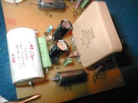
Ricardo, I put a .15u russian cap in the interstage coupling position, and then another one on the output, in parallel with two 1u (sprague pio).
Hope it goes well for you.
Hope it goes well for you.
Hi Salas
Can I use a 16v cap in C6 ?
What is the maximum voltage there ?
Almost done...!!!
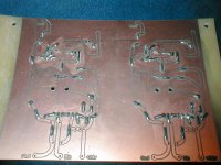
After all the board does not have a common GND between channels.... Lee left the copper all around the circuit... like a mask... should I ground this "virtual gnd" ?
Regards
Ricardo
Can I use a 16v cap in C6 ?
What is the maximum voltage there ?
Almost done...!!!
After all the board does not have a common GND between channels.... Lee left the copper all around the circuit... like a mask... should I ground this "virtual gnd" ?
Regards
Ricardo
Yes you can, the Zener is for 8.2V there. So C6 can safely be 16V.
Actual ground traces I would connect from phono channels to the shunt's reg out GND like a Y. And from there, with one cable to chassis. The masks I would connect locally to the ground traces where the cables to reg GND take off. Off course all this may change if you face some GND loop (I wish not).
Photos, first impressions etc. I don't have to remind I guess...😀
Thank you Salas
My plan was to build a central star GND and then route there all the following GND five wires:
Shunt - one wire to star
Riaa (both left and right GND plus another wire for the screen) - three wires to star
Output rca - two wires to star
I plan to solder the input rca directly to the riaa board.
Is this a good idea ?
Ricardo
Yes its a standard star. So it must be good. You must start with something. If you don't get buzz, you will be practically OK. Make it so we know. Final countdown? When ready?
I hope that the PIO in the RIAA filter is in good tolerance...
Where is your C3? This one is the most RIAA critical. Must be 15.8nF-16nF measured and matched if possible.
Where is your C3? This one is the most RIAA critical. Must be 15.8nF-16nF measured and matched if possible.

- Home
- Source & Line
- Analogue Source
- Simplistic NJFET RIAA