RCruz said:
Hi Salas
I will use this schematic to start with.
http://www.diyaudio.com/forums/showthread.php?postid=1658735#post1658735
As I can not find the transistor BC550BP.... can I use BC550C for Q3 ?
Ricardo
BP just means bipolar🙂 There is BC550B and 550C. The C grade has the strongest hfe and its the better option, although the B would not cause any serious performance loss if someone happens not to finding the C easily. If your DMM has an hfe socket and measures it, you can match them 550Cs for hfe. Not critical, but slightly better practice in our case. In general my experience from Philips and Toshiba 550Cs says that they come close enough in hfe without matching.
Ricardo, I couldn't find the BC550C so I used the BC550B with no perceived ill effects. You can always replace it later if you don't have it now on hand.
Salas, a question for you. Do you think it would be worth to driving the power mosfets in the shunt with a higher current? There are some that recommend a driver capable of delivering the gate current fast and high enough, as per the following formula:
I = 100 * Qg * f
which, for the IRFP9240, with the Qg = 44 nC, and choosing a frequency as high as 50kHz,
I = 100 * 44E-9 * 50E3 = 220 mA
Any thoughts on this?
There's an article about this at
http://sound.westhost.com/articles/hexfet.htm
and a number of application notes about the importance of driving the power mosfets with enough gate current.
Its working already with 230mA with R1=6R8 as recommended.😉
I was telling in previous posts that I prefer it from 200-250mA if someone wants to sink it enough. Although subjectively there is a small gain from 100 to 200mA.
I was telling in previous posts that I prefer it from 200-250mA if someone wants to sink it enough. Although subjectively there is a small gain from 100 to 200mA.
I was talking about the bjt driver's bias, at 220mA. Not the mosfet itself, which, yes, is already working at around 250mA. Perhaps I misunderstood the article and app notes.
It would not be practical. We would need a power transistor, and then its hfe would be many orders lower than a BC550 so the regulation would slack a lot.
ikoflexer said:I was talking about the bjt driver's bias, at 220mA.
I don't know if we need square wave grade - no higher order harmonic producing performance for the shunt, as in perfect class A driver for 50kHz in that full audio amp example in the article, but I know that our ripple frequency will be either 100Hz or 120Hz. So If we even want to satisfy the article's criteria, we must calculate for 50.000Hz/100Hz = 1/500 lower bias current? If yes, 220mA/500=0.44mA. We already run the driving BC550 at 3.3mA for example.
salas said:
I don't know if we need square wave grade - no higher order harmonic producing performance for the shunt, as in perfect class A driver for 50kHz in that full audio amp example in the article, but I know that our ripple frequency will be either 100Hz or 120Hz. So If we even want to satisfy the article's criteria, we must calculate for 50.000Hz/100Hz = 1/500 lower bias current? If yes, 220mA/500=0.44mA. We already run the driving BC550 at 3.3mA for example.
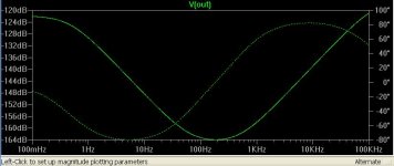
I agree that for the main line ripple freq of 100Hz or 120Hz this applies. However, we should probably not dismiss higher frequencies which can appear, for some people can be switching diode noise, or any other high freq noise that can occur from other components. For example, inserting an lt1010 buffer right before the gate resistor of the right most power mosfet brings the psrr and output impedance to new lows, in simulation. Now I really wish I had a sound card like yours to run some real measurements. Not that your shunt regulator really needs it, as it is an outstanding performer. But you know how it is, if there is even a bit of room for improvement (for me at a low cost), I would do it . I'd like to try a simple push-pull discrete buffer also, I'll post results if I get any.
If you try that one with the current mirror in simulation, it shows no ripple at all. Maybe you want to look at it too? It only uses one more transistor. I don't know for chasing everything that may occur in the DC input line, but I haven't seen more than a fast op amp driving element even in the most documented and top performance regs, so driving in the hundreds of mAmps must not be of particular merit in our case. We can make it better and better, but I don't know what complexity and feedback may subjectively bring. Open, but out of the ''simplistic'' I guess. Nice to make non the less.
I'm not pushing for it or anything, just throwing some ideas around. Can't stop tweaking, you know how it goes.
See this in your sim and tell me your opinion. Still not a loop feedback one. The current mirror automatically adds 2 local feedback mechanisms mind you. Its OK if you want to experiment. I like it too. Most people will go for the simplest adequate anyway.
Attachments
ikoflexer said:I'm not pushing for it or anything, just throwing some ideas around. Can't stop tweaking, you know how it goes.
Yes I know.😉 What about your actual sound till now? Opened up with use at all?
The sound is nice. I'm still giving it some more time, as I just replaced the output caps with the nos sprague pio. However, I can already say that the sound overall has improved a lot over whatever I used previously. It is good that I came across your design.
I'll try the current mirror this evening.
I'll try the current mirror this evening.
Can we use just a source follower jfet buffer with good enough results instead of a high loop feedback and internally complex op amp? Or lags far behind in performance? Can you sim such an idea so to know? Also which one does better with the buffer? The LED ICCS current mirror one or the Vbe ICCS current mirror one?
I've tried a number of simple discrete buffers and just can't get them to play well with the rest of the circuit. I too would prefer not to use an opamp. I tried it just for laughs... but I'm not laughing at it now.
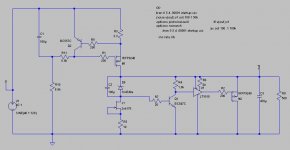
Attached is the schematic that produced the curves posted a little earlier.
Attached is the schematic that produced the curves posted a little earlier.
Attachments
- Home
- Source & Line
- Analogue Source
- Simplistic NJFET RIAA