can you suggest me a schematic?
i have a few low idss (below 6ma) 2sk170 and y would like to try something
i have a few low idss (below 6ma) 2sk170 and y would like to try something
no...didn`t finished the project.i`ve started another one(pcm1794 dac)
someone promised me a wood box for the phono and i`m waiting for that
someone promised me a wood box for the phono and i`m waiting for that
can you suggest me a schematic?
i have a few low idss (below 6ma) 2sk170 and y would like to try something
It will take much current driving 32 Ohm for using just Jfets. Not suitable.
no...didn`t finished the project.i`ve started another one(pcm1794 dac)
someone promised me a wood box for the phono and i`m waiting for that
Better metal box for phono. Or line the wood with earthed copper sheets inside.
jFETs generally like higher volatges to work with. 18V to 27V is a good range. The voltage sound to low to be usuable.a friend of mine bought today a pair of 32 ohm headphones rated at 1.5w input power.i would like to make s surprise with building him a simple portable headphone amp.
saw somewhere one powered from 3.6v 1200mah lithium accumulator but was with bjt.
do you think 2sk170 will work at such a low voltage(3-3.7v)?
Hi Salas, Merlin, Ricardo
I haven't been on the net for a while, so just catching up.
It's been like an igloo in my workshop over the winter.
Too cold for DIY.
Am thinking about chassis making and woodwork now the summers on it's way.
Hope the DIY's going well and the music sounding sweet for you all.
Those cool tall drinks Salas has got there look good.
Hope to be enjoying a couple of those in the sun soon myself with some good tunes.
Cheers
Simon
Hi schultzsch-
Check out wikipedia to get a nice intro on jfets and fet's in general. I found this link there, a nice little controllable animation on how a jfet works. Great for visual types (me) and helps you get your noggin wrapped around concepts better. 😀
http://www-g.eng.cam.ac.uk/mmg/teaching/linearcircuits/jfet.html
-Kent (which is still snowed under with work but going to get back to his Salas RIAA soon!)
Salas i was thinking about that too,do you have any idea how thick the copper foil should be?(what happens if i use aluminium foil instead copper,to be more precise i want to use the kind of foil that my mom uses in kitchen 😀)
thank you kstlfido
i`ll check that out
thank you kstlfido
i`ll check that out
It will take much current driving 32 Ohm for using just Jfets. Not suitable.
And be suitable for 300 Ohms like my Sennsheiser?
Hi Salas, Merlin, Ricardo
I haven't been on the net for a while, so just catching up.
It's been like an igloo in my workshop over the winter.
Too cold for DIY.
Am thinking about chassis making and woodwork now the summers on it's way.
Hope the DIY's going well and the music sounding sweet for you all.
Those cool tall drinks Salas has got there look good.
Hope to be enjoying a couple of those in the sun soon myself with some good tunes.
Cheers
Simon
Hey Simon, I'm glad to hear you again🙂
Hi
i use on my riaa pre as output caps 2.2uf wima polystyrene,i have another two wima polypropylene caps but they are at 1uf each.the load impedance of my line pre is 100k.
after a close look at Coupling Capacitor Calculator by V-Cap i think i can use the two 1uf wima with Optimal low frequency response (Hz): 16.00
is this right? should it sound better with polypropylene caps?
1uF on 100K looks good given the phono's self roll off included. 0.47uF still looks good on 100K if you got by any chance and saves even more disc warp movements amplification in the very low region. What should sound better as for capacitor quality beyond proper value chosen, is up to your ears and preference in the context of your system. You will tell.
mmm...finished
at first impresion sounds more detailed but i`m not shure yet.guess i`ll have to do more listening...
at first impresion sounds more detailed but i`m not shure yet.guess i`ll have to do more listening...
Measuring Vp
Briefly free from a work spell, so time to tinker! I'm trying to come up with a quick test for Vp. Google search reveals many ways to do this, some rather involved.
I've attached two similar simple measurement techniques- the first is off the run-off-groove site, the second is from the Erno Borbely paper on jfets.
The Borbely tester uses a bi-polar power supply. Is this necessary? I have one, but but it's buried. All I have right now is a dual 0 to 6vdc supply I'm connecting in series to get 9vdc.
I appreciate any help on the matter.
Thanks- Kent
Attachments
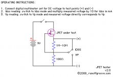
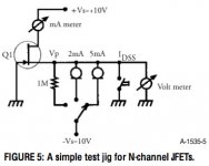
compare the two diagrams.
with left switch to Idss the 1M is shorted out and the voltmeter reads the voltage across the 100r. That is the same as the right with the Idss switch closed.
The main difference between these two settings is where the current is measured. on the left the voltage across the 100r lets you see the current easily. The right can use an ammeter or preferably a 100r and the another voltmeter.
Now switch the left to Vp. The 100r is shorted out and the voltmeter measures the voltage across the 1M. There is a problem that I will come back to.
The right uses the switched 1M for a voltmeter reading. Note there is no other current flowing to that ground. It is a floating ground that is only used by the voltmeter. Effectively you have a single polarity supply of double the voltage. It is effectively the same circuit as the left most diagram.
Now the problem:
A voltmeter is usually specified with an input resistance/impedance. A DMM can be anywhere between 1M and 100M and very common to see 9M or 10M as input impedance.
measuring the voltage drop across a 100r resistor with a 9M voltmeter results in a tiny under-read of the voltage The actual resistance is reduced to ~99.999ohms (the last 9 is actually 88 repeating).
You are measuring the voltage across 99r999 and you can see that the current value is so close to the assumed 100r resistor value prediction that we normally ignore the under-read and assume it is accurate.
When measuring the voltage across 1M with a 9M voltmeter, the under-read is gross.
The effective resistance is 1M//9M =900k.
The voltmeter reads the voltage across a 900k resistor but you think you have read the voltage across a 1M resistor. There is a 10% under-read. If you want 1% accuracy you must take account of the voltmeter resistance whenever the test resistor is within 1% of the voltmeter input resistance. This would apply whenever you measure the voltage across >=100k for a normal DMM. With a 10M load for measuring VP the error is much higher. The reading is almost worthless without taking account of the correction.
For matching purposes I would use the left one with 1M, which is handier. Works with just one battery, and will show same deviation % error from absolute real Vp for all samples. I would not use its IDSS function, I still prefer a straight in line Ameter for that. When the IDSS is much different, the drop on 100R changes the VDS enough and affects the standard. Say you have a range of 6mA to 15mA JFETs to test for IDSS, that would change VDS from 8.4V to 7.5V for a 9V battery.
- Home
- Source & Line
- Analogue Source
- Simplistic NJFET RIAA