If you shorted S0-F0 and NOT shorted S+ - F+, the regulator part and shunt FET not working.
In this case CCS can be tested with low DC voltage.
Use 10-12V input voltage and measure CCS current via F0-F+ with current meter.
12V*0.065A= 0.78W so CCS with even small heatsink can be tested.
If CCS working well (for example 65mA, as above), try to test with dummy load: 4k7 10-25W.
Sample:

In this case CCS can be tested with low DC voltage.
Use 10-12V input voltage and measure CCS current via F0-F+ with current meter.
12V*0.065A= 0.78W so CCS with even small heatsink can be tested.
If CCS working well (for example 65mA, as above), try to test with dummy load: 4k7 10-25W.
Sample:
Verified, only cut a ground wire from signal ground to chassis ground.The Valve Itch also has a heater lift voltage divider for the mu follower. Could there have been an accidental mix of ground and lift voltage node?
Last edited:
If you shorted S0-F0 and NOT shorted S+ - F+, the regulator part and shunt FET not working.
In this case CCS can be tested with low DC voltage.
Use 10-12V input voltage and measure CCS current via F0-F+ with current meter.
12V*0.065A= 0.78W so CCS with even small heatsink can be tested.
If CCS working well (for example 65mA, as above), try to test with dummy load: 4k7 10-25W.
Sample:
View attachment 1132695
CCS is working ok: with trimmer got near 100mA, tomorrow I will try the 4K7 10W as dummy load.
It seems works well: max. 262V with 5k dummy load = 52mA also can decrease volts and mA CCS using both trimmers
Practical rule of the thumb:
CCS current must be -at least- load current+10% (if the 10% is lower than 10mA, then 10mA).
If the load is 45mA, then must to set CCS to 55mA.
CCS current must be -at least- load current+10% (if the 10% is lower than 10mA, then 10mA).
If the load is 45mA, then must to set CCS to 55mA.
The load is 25mA Valve Itch + 20mA SSHV2 self consumption total 45mA. The CCS is upper IXTP 01N100D & lower DN2540.
Felipe,
If the CCS is working (#6663) and the all SSHV2 working too (#6664) what's the problem?
Set CCS to 41mA (the shunt current will be about 12.2mA, the other parts currents 3.8mA, so the regulator part current 16mA).
Set input voltage of SSHV2 to 280V.
Try dummy load for -about- 25mA: 220V/0.025A=8k8
Set SSHV2 pot until output is to 220V.
If the valve real current is 25mA, the output voltage of SSHV2 will be around 220V. Correct it with potentiometer.
I don't know what's the problem Bela, but to have 45mA CCS I have to reduce SSHV2 to 269 Vout & Valve Itch needs 300V & 45 mA!!!!
If Vout is more than 269V the CCS stars to reduce it, if I set 300 Vout the CCS is 22mA only.
Of course the CCS trimmer is set to max. mA
Now CCS is working with two cascoded DN2540 as per Salas design.
If Vout is more than 269V the CCS stars to reduce it, if I set 300 Vout the CCS is 22mA only.
Of course the CCS trimmer is set to max. mA
Now CCS is working with two cascoded DN2540 as per Salas design.
I'm confused.
Please read exactly these parameters.
Output voltage of SSHV2 (load voltage):
Load current:
Input voltage of SSHV2:
Please read exactly these parameters.
Output voltage of SSHV2 (load voltage):
Load current:
Input voltage of SSHV2:
It's difficult for me to express in English sorry.
The problem is: I can't set the SSHV2 CCS to 45mA only max. 22mA with a load of 300V.
Playing with the SSHV2 I noted that if I lower the load to 269V I have a CCS of 45mA.
SSHV2 Vin 273V when load Vout is 269V and CCS is 45mA
The problem is: I can't set the SSHV2 CCS to 45mA only max. 22mA with a load of 300V.
Playing with the SSHV2 I noted that if I lower the load to 269V I have a CCS of 45mA.
SSHV2 Vin 273V when load Vout is 269V and CCS is 45mA
Last edited:
Insufficient HV raw supply.
I asked you in #6655:
"Is HV raw supply (especially PT secondary) has enough current capacity?
Did you test it with dummy load?"
You wrote:
"PT 250VAC 0.2A.
No.
I guess yes, target B+ is 300V."
With tube rectifier (even in hybrid layout and CLC smoothing) it will never produce 300V DC SSHV2 output at 45mA load.
Requiring raw voltage = 300V + 30V CCS headroom aka. 330V at SSHV2 input.
You measured it perfectly:
"I can't set the SSHV2 CCS to 45mA only max. 22mA with a load of 300V."

It's the physic.
-----------------------------
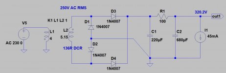
First of all, test PT as attached pics shows.
If it only 250V AC with load, it's the bottleneck.
----------------------------
BTW "Valve itch phono" current requirement is 25mA????
In the schematic 1mA+6mA= 7mA per side, so overall requirement only 14mA.
If it's true, the SSHV2 CCS current settings to 25mA is perfect.
I asked you in #6655:
"Is HV raw supply (especially PT secondary) has enough current capacity?
Did you test it with dummy load?"
You wrote:
"PT 250VAC 0.2A.
No.
I guess yes, target B+ is 300V."
With tube rectifier (even in hybrid layout and CLC smoothing) it will never produce 300V DC SSHV2 output at 45mA load.
Requiring raw voltage = 300V + 30V CCS headroom aka. 330V at SSHV2 input.
You measured it perfectly:
"I can't set the SSHV2 CCS to 45mA only max. 22mA with a load of 300V."
It's the physic.
-----------------------------
First of all, test PT as attached pics shows.
If it only 250V AC with load, it's the bottleneck.
----------------------------
BTW "Valve itch phono" current requirement is 25mA????
In the schematic 1mA+6mA= 7mA per side, so overall requirement only 14mA.
If it's true, the SSHV2 CCS current settings to 25mA is perfect.
Last edited:
Bela mine PSU it's very similar CRC 0,47uF-1R-820uF without chokeInsufficient HV raw supply.
I asked you in #6655:
"Is HV raw supply (especially PT secondary) has enough current capacity?
Did you test it with dummy load?"
You wrote:
"PT 250VAC 0.2A.
No.
I guess yes, target B+ is 300V."
With tube rectifier (even in hybrid layout and CLC smoothing) it will never produce 300V DC SSHV2 output at 45mA load.
Requiring raw voltage = 300V + 30V CCS headroom aka. 330V at SSHV2 input.
You measured it perfectly:
"I can't set the SSHV2 CCS to 45mA only max. 22mA with a load of 300V."
First of all, test PT as attached pics shows.
View attachment 1133046
----------------------------
BTW "Valve itch phono" current requirement is 25mA????
In the schematic 1mA+6mA= 7mA per side, so overall requirement only 14mA.
If it's true, the SSHV2 CCS current settings to 25mA is perfect.
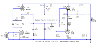
Surely Salas told me to set the SSHV2 to 45mA, mine Valve Itch uses other valves and the schematic is a little bit modified. Attached schematic, if I remember correctly the 7N7 runs at circa 9mA each so 9 x 2 = 18mA + 2mA each E283CC total 20mA + 20mA SSHV2 self consum = 40mA near Salas advice.
Attachments
Ooops....Bela mine PSU it's very similar CRC 0,47uF-1R-820uF without choke
0.47uF ?????
Rather 47uF!
But it's the beauty spot, 1R-820uF is a dominant (100mA charging spikes stresses tube rectifier).
It's not SS PSU, the 1R-680uF is very hard load for AZ1.
Try to use choke.
- Home
- Amplifiers
- Power Supplies
- Simplistic mosFET HV Shunt Regs