Sounds pretty catastrophic. Maybe an insulation issue or a PCB issue? An arc? I don't know this green PCB you showed.
In your shoes I would either follow the whole troubleshooting procedure link going down to last components like Zeners and trimmer, after inspecting and cleaning the board thoroughly, or simply restart and build new with a clean slate but with fuses on its input and output this time. Slow blow ones of comparable value to the CC setting.
Also by using a fat Schottky diode instead of the Zener (the one near the JFET). If planing to transplant some parts, trust only those that will measure OK off board on their own with DMM and transistor tester.
I measured the voltage at each stage again and found that when input goes higher than 230V, the voltage at C1 dropped to lower than 20V. So it should be Q1, Q2 have problem. As I don't have any more spares, need to order some and try again later.
There are some IXYS HV DMOS options too. MJE350 can substitute any dead Q4 Q5 also if available locally. Lower spec option but good enough for proof testing.
P.S. Also try one of those transistor testers with the ZIF socket and little LCD screen found everywhere online. They are good enough for recognizing semiconductor types, sorting out working or dead ones, comparing some parameters etc. They are very cheap and can be helpful.
All semiconductors ordered and will be delivered tomorrow. As per your recommendation, I bought a Chinese transistor tester at only $8.

Hi Salas
Finally I got all the semiconductors and replaced Q1, Q2, D1 and D2 but the symphony still the same. The voltage measured at C1 goes up to 23xV then drop to 0V, input still has 26xV. Q1 became very warm >50degC.
What show I do?
Finally I got all the semiconductors and replaced Q1, Q2, D1 and D2 but the symphony still the same. The voltage measured at C1 goes up to 23xV then drop to 0V, input still has 26xV. Q1 became very warm >50degC.
What show I do?
Hi,
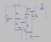
I bought a kit for a SSHV psu a few years ago, and now I want to use it in a high output Z, cathode follower, OTL topology headphone amp with one 12au7 and one 6080 tube. I need 170v output, and have a 150v transformer. How much filtering should I use, and how do I set the right output? Could anyone help me estimate the current this amp needs?
I bought a kit for a SSHV psu a few years ago, and now I want to use it in a high output Z, cathode follower, OTL topology headphone amp with one 12au7 and one 6080 tube. I need 170v output, and have a 150v transformer. How much filtering should I use, and how do I set the right output? Could anyone help me estimate the current this amp needs?
Impossible for anyone to estimate without a schematic at least. You should measure the current consumption of the client circuit with an Ameter between PSU and B+ input first. If its built and has a PSU as it is. You add 20mA to the reading for the shunt's bias and calculations. With PSUD2 software simulator from Duncanamps.com you can enter the Tx data and decide configuration and filtering of the raw DC part so it drops to 190V DCin when the SSHV2 powering the client circuit is involved.
Here is the schematic. I am rebuilding an existing pre amp to make this. If no one can calculate the current I will just make it after a schematic first and measure.
Thank you!

If the voltages are to be believed, each channel will run 33mA for the 6080. Not sure how to calculate the current in the LED biased 12AU7 but it won't be much. If you shoot for 70mA plus 20mA for the shunt reg, that should be OK I think.
Not sure how to calculate the current in the LED biased 12AU7...
Look at the schematic. B+ is 170 V, 12AU7 plate is at 90 V thru a 22k1 resistor.
Ohm's law says: Ip = (170V-90V)/22.1k = 3.6 mA
I need 170v output, and have a 150v transformer. How much filtering should I use, and how do I set the right output? Could anyone help me estimate the current this amp needs?
After rectification and filtering (220...470 uF) you get ~200 V as raw DC. You need 170 V for the amplifier, so shunt regulator should "dispose" 30 V.
According to the schematic, the total current consumption for two channels are 74 mA.
I this were my project (and must use shunt reg.), I would use this:
Attachments
Ok, thank you!
I wanted to try the shunt reg since I had it lying around, and assumed it was a better solution than a regular psu, but do you disagree, artosalo?
Another question not directly related to this is my next project, a clone of the wheatfield ha-2. If I find the shunt to work better than the regular psu in this amplifier, is there any reasonable way to make a similar shunt for a bigger current?
Thank you again for the help!
...assumed it was a better solution than a regular psu
What do you mean with regular psu ? Unregulated psu or psu with series regulator ?
Your 6080 require quite high current and therefore the power loss in shunt regulator is relatively high. With series regulator the power loss would be smaller.
In this kind of projects I would use a power supply with series regulator such as "Maida"-type. I have understood that shunt regulators are used mainly with pre-amps and other lower current projects.
One application of this type of regulated supply would be in a case where you have very low PSRR, as in simple single-ended gain stages. I agree, a 6080, even at relatively low current of 33mA, may not be a great choice for this regulator. But it MIGHT serve well for the driver stage. Phono stage would be another great application.
Clean the board very well. Remove Zeners.
Hi Salas
The SSHV2 works perfectly after removed the Zeners. Should I re-install the Zeners with other rating?
- Home
- Amplifiers
- Power Supplies
- Simplistic mosFET HV Shunt Regs