Can there be some solder bridge or flux residue on the PCB?
I will clean.
Salas to test the CCS alone it's only necessary to take off R7 and connect F+ & F0 to a 100-220R dummy load?
To only short F+ with F0 is enoughSalas to test the CCS alone it's only necessary to take off R7 and connect F+ & F0 to a 100-220R dummy load?
![WP_20170221_001[1].jpg](/community/data/attachments/546/546153-39e5f75d55a28cff62039cf146ea9caf.jpg?hash=OeX3XVWijP)
![WP_20170221_002[1].jpg](/community/data/attachments/546/546169-a52dd2fc690e1b2fe9cd3f73a3b48374.jpg?hash=pS3S_GkOGy)
Can put 4.7k across each 68k, feed 30V input from lab supply and see if the output can adjust to 22V on 2200R dummy. That would be a full LV test. If successful remove the 4.7k resistors and set the reg for its HV duty.
![WP_20170221_003[1].jpg](/community/data/attachments/546/546741-4b90ca2a9554e0c613a76ef173b0fa2a.jpg?hash=S5DKKpVU4M)
Slave Regulator vs SSHV2
Dear Salas,
Assume the master regulator retain in the power supply, what would happen if replacing the slave regulator (the one close to signal path) with your SSHV2?
What the differences between slave regulator and your SSHV2 for this application?
Thanks!
Dear Salas,
Assume the master regulator retain in the power supply, what would happen if replacing the slave regulator (the one close to signal path) with your SSHV2?
What the differences between slave regulator and your SSHV2 for this application?
Thanks!
Attachments
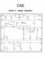

Its little CCS range for Q1 & Q2 nonetheless. They usually go up to about 100mA in this arrangement. Measure R5. Is it 10R indeed? If no and its higher by mistake restore to 10R. If yes its 10R, weird CCS result if so, try 1R (1mV=1mA TP). Also check if R4 trimmer & R3 resistor are good.
- Home
- Amplifiers
- Power Supplies
- Simplistic mosFET HV Shunt Regs