Hi Salas.
What do you think about using this cap for C2?
http://uk.farnell.com/panasonic/ezpe80106lta/cap-film-pp-10uf-800v-rad/dp/2192337
What do you think about using this cap for C2?
http://uk.farnell.com/panasonic/ezpe80106lta/cap-film-pp-10uf-800v-rad/dp/2192337
Last edited:
Pretty expensive, but you will probably find that a PP motor run cap is just as expensive.
It may be worth buying MKT to make a comparison.
You could also buy some 22uF non polar electrolytics and series connect them.
You may find they perform just as well.
And
It may be worth buying MKT to make a comparison.
You could also buy some 22uF non polar electrolytics and series connect them.
You may find they perform just as well.
And
Hi Salas.
What do you think about using this cap for C2?
EZPE80106LTA - PANASONIC - CAP, FILM, PP, 10UF, 800V, RAD | Farnell UK
I am not impressed by its ~0.8 1kHz tanδ(%) @ 10uF. Wima MKP10 has <3x10^-4 ( 0.0003 ).
Thanks Salas and Andrew for your input. I have some high voltage electros-i'll try them against an MKP.
Well... Where did you get the numbers?I am not impressed by its ~0.8 1kHz tanδ(%) @ 10uF. Wima MKP10 has <3x10^-4 ( 0.0003 ).
Here:
http://www.farnell.com/datasheets/1644446.pdf
EZPE80106LTA has tanδ(%) 0.22 @1kHz. In absolute numbers it is 0.0022.
Here:
http://www.wima.com/EN/WIMA_MKP_10.pdf
for MKP10 series and C>1uF: tanδ (already in absolute numbers) is 0.0003.
Well... Where did you get the numbers?
From this chart in its datasheet. 0.08 (not 0.8, typo).
Attachments
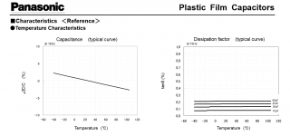
But it is % (in case of Panasonic), and absolute numbers (in case of Wima). To compare them you should use both absolute or both %% numbers.
i built SSHV2 but I'm not sure if it's a OK or not. the led is only on when I attached the DVM probe. When I remove the probe, the led is off...
When connected to the probe I can adjust current and voltage, but I'm not sure if this is OK or not..
When connected to the probe I can adjust current and voltage, but I'm not sure if this is OK or not..
Do you use a correct dummy load? Are all 4 wires connected to it? Is it a point to point or a standard pcb build?
I built a pcb based on your PCB pict on page 207... I short the output and sensing pad.. using Vin 198V and setting for 165V @22mA (intended to use it for 26 Pre) and use 7500Ohm 50W as dummy. Bought all the component from Tea Bag (except for the PCB)
You should set at 42mA. You leave not enough spare current for the parallel section to run on when setting CCS at 22mA for a 22mA dummy load.
Hi guys,
I built the HV pcb Kit from you. It sounds amazing, however mine only ran for a short while.
I am running it at 300V output and 50mA.
It seems that my heatsink was not up to the job and I overheated the transistor - I measured 75-80 Deg on the sink a few minutes before it went silent.
I only get 85V output now, so that's gone.
Ordered a replacement transistor and a large heatsink. However, do you suspect other parts might have gone in this except the transistor? I would like to order all the replacements so I can get it all done at once.
What is the temperature the heatsink should stabilise at?
Thank you and congrats on the design and kit.
Andrei
There is a big chance that some other semis went south. The fastest method I use now is to take them all off and measure them, even if it doesn' t seem it is.
You are going to waist more time if you just change one and then it doesn' t work again. There is also a chance that you burn some more on the process, so I say take all of them off.
Also make sure that you have enough heatsinking. Remember that sinks inside cases are not so effective.
You are going to waist more time if you just change one and then it doesn' t work again. There is also a chance that you burn some more on the process, so I say take all of them off.
Also make sure that you have enough heatsinking. Remember that sinks inside cases are not so effective.
Thanks for the advice. . . I feared this would be the case but hoped I would get away with it 🙁
I will try to sort out another full set of parts for it - can't wait to get it up and running again.
Regards,
Andrei
I will try to sort out another full set of parts for it - can't wait to get it up and running again.
Regards,
Andrei
Do you have a good way of taking out parts from this PCB? The plates holes are a pain and 3 pin devices are hard to extract without overheating 🙁
You will need a desoldering pump, solder wick and if you google a little bit :
https://www.google.gr/search?q=deso...l5.4064j0j7&sourceid=chrome&es_sm=93&ie=UTF-8
https://www.google.gr/search?q=deso...l5.4064j0j7&sourceid=chrome&es_sm=93&ie=UTF-8
- Home
- Amplifiers
- Power Supplies
- Simplistic mosFET HV Shunt Regs