The HIFI2000 website needs revision to more intuitive and comprehensive IMHO.
I'd second that.
P.S. La Porxada, is that a nice place for tapas? 😀
I don't know if still exist, the lighter have 19 yeas old when I was living in Barcelona and yes the chef was excellent......
Pictures for Salas
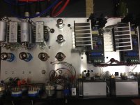
Almost done with my compressor, still trying to sort out the last instability issues at fast compression, but it's almost there. Last bits, just adding a SS/valve side chain switch.
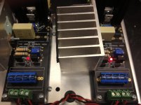
Promised some photos so here you go! It's going into Ocean Sound Studios in Alesund, Norway. New mix room being built there and this will be the first custom unit 🙂
One question - the LEDs on both boards are the same type but one shines brighter than the other, is this something to be concerned with? The boards are running very well, but thought i'd ask anyway.
Thanks for your efforts!
Charlie
Almost done with my compressor, still trying to sort out the last instability issues at fast compression, but it's almost there. Last bits, just adding a SS/valve side chain switch.
Promised some photos so here you go! It's going into Ocean Sound Studios in Alesund, Norway. New mix room being built there and this will be the first custom unit 🙂
One question - the LEDs on both boards are the same type but one shines brighter than the other, is this something to be concerned with? The boards are running very well, but thought i'd ask anyway.
Thanks for your efforts!
Charlie
Attachments
With the SSHV2 how hard is the 400V limit? I'm looking at 400V 30 ma op +20 ma, big heatsink so OK there but what sets the 400V max ?
Pictures for Salas
....
One question - the LEDs on both boards are the same type but one shines brighter than the other, is this something to be concerned with? The boards are running very well, but thought i'd ask anyway.
Thanks for your efforts!
Charlie
Nice stuff. Congrats on your custom soft knee valve compressor.
For same output voltage there ought to be same current set via the Jfet sources that runs through the LED to the Vref 68K resistors. Therefore same type leds should shine about the same excluding some possible luminosity variation from sample to sample. Just because there are two circuits and two regs, try to scope if there is something different going on with sense points or there is some VHF oscillation in one that finds its way back and the higher brightness is a clue. Or the dimmer brightness for that matter.
I have tested all the points and they all read the same. My scope isn't great but it doesn't look like there is any VHF oscillation. Unless there is on both boards - it just looks like noise to me. About 2mV - is that about right for this reg?
If there is oscillation what might be the issue? A ground loop?
Thanks!
Charlie
If there is oscillation what might be the issue? A ground loop?
Thanks!
Charlie
With the SSHV2 how hard is the 400V limit? I'm looking at 400V 30 ma op +20 ma, big heatsink so OK there but what sets the 400V max ?
Its the spec of the upper cascode DMOS that recommends no more than 400Vin. The output Enhancement Mode 842 has 500V spec already. And there are the PCB isolation distances being challenged, heat rising on output MOS and the cascode BJTs the more you push it up, transients can be hard etc. Roger57 had installed and tested a 500V Q1 with success, see posts #3397-3406.
I have tested all the points and they all read the same. My scope isn't great but it doesn't look like there is any VHF oscillation. Unless there is on both boards - it just looks like noise to me. About 2mV - is that about right for this reg?
If there is oscillation what might be the issue? A ground loop?
Thanks!
Charlie
When on a rail AC coupled to a scope and seeing a straight line, then 2mV Pk-Pk thickness of random nature can be anything radiated in the total circuitry or picking environmentally by the test loop, it would not alert. If not seeing any waveforms riding then it should be stable. Is it the same display on the sense outlets on the regs themselves?
OK I understand. Yes the same display is on all sense points on both regs.
Going as close as I can with the scope there is a ripple of about 620KHz on both boards, but as you say - it may be something else I am picking up. There is certainly nothing on one board that is not present on the other.
Going as close as I can with the scope there is a ripple of about 620KHz on both boards, but as you say - it may be something else I am picking up. There is certainly nothing on one board that is not present on the other.
It's so faint, hard to tell really - but I would say a sinewave of 2mV p-p @620-680KHz on all sense points.
Is there anything in series on the load's rails? An interfacing RC for instance or some local decoupling?
No, there is no RC after the regs, just the filter at the reg input that solved my stability issue.
Try a test RC 10R in series and 0.47u to ground at remote load side. See if it changes something. Just to be sure there is no residual.
P.S. If you got the probe open on air laying somewhere, is that thing still there with same scope settings? If you short the probe tip with its gnd crock is it better?
Hi Regal!With the SSHV2 how hard is the 400V limit?
Once accidentally put 450V to my tested (point to point wired SSHV2) CCS modul. Upper DN2540 immediatelly died. :-(
Why not use IXTP01N100D (1000V, 100mA) instead of upper DN2540?
Mouser sell it for $4.73.
Not sure if it can provide the same max IDSS but that is not relevant to most builds using moderate CCS. Also I would not trust the TO-220 or our PCB creepage distances beyond 500V. Not to mention 1000V the IXYS is specified for. Sure that its silicone die spec can take it is good transient margin distance nonetheless.
Thanks I will try the RC on Reg output and come back. There is an individual RC on input on each reg.
I just picked up a new probe as mine is getting old and the ripple is much better so maybe it was just a bad probe..
I just picked up a new probe as mine is getting old and the ripple is much better so maybe it was just a bad probe..
- Home
- Amplifiers
- Power Supplies
- Simplistic mosFET HV Shunt Regs