It is very strange but second salas work fine, they are the same.. 17K dummy load (15mA 260v) Tp set on 350mV.
Hi Salas, wishes of happy new year.
I need your help if possible, yesterday working late and tired, I did a stupid mistake with one working SSHV2 board, I connected my meter probes set to measure on the 20A range, to the output of the board, wanting to measure voltage 😡
Of course this produced a nice small flash on the terminals/probes, and the regulator stopped working. The led is still on, but now I get only around 6,4V on the output.
What I need is for you to tell me in your opinion what should be changed to avoid taking all transistors out.
Many thanks.
Check Vgs and Vbe on all semis to pinpoint broken ones.
It is very strange but second salas work fine, they are the same.. 17K dummy load (15mA 260v) Tp set on 350mV.
Check the semis, look for little differences between your 2 executions. Cleaning, wiring, whatever you can observe. Can't tell much out of experience on boards I have no hands on knowledge of.
Probably R4 was broken. I will change R1,R11 and R4 and i will be good, mayby. The second salas works fine , allready for 25minutes.
Gate stopper should be on 840's pin, and avoid as much cable length as possible. Check if you got any fail in insulation to sinks in the non working one also.
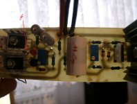
Thanks for a help, they are not mje350, they are ksa 1381, fully isolatet from sinck's. This is pasible that R4 was broken before I add power suply, When im measuring it it got still 500R( I haved use 500R) .
Salas,
I still owe you a picture of AZ1 with black meshies...
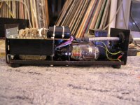
Shunt works fine now after replacing the semis altogether, very good sound with D3a phono/silk stepups, I raped PCB from Quanghao, and built it with different circuit.
Unfortunately my digicam broke, so no pics of the internals of the actual phono stage, only unfinished with SSHV1.
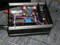
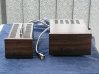
Enclosures are from fleamarket (5€), little spray, mdf, veneer, some evenings spare time.
Sure enough I am going to put those regs everywhere possible, big upgrade everytime I use them.
BTW I bought a Peakatlas transistor tester, very useful to sort out the dead from the alive😎 . Before I had to throw away the suspected semis , now I can check out the actual culprit and keep the healthy ones.
So thanks one more time for spending all this time here to help out those helpless guys fixing their burnt regs ...
cheers,
Juergen
I still owe you a picture of AZ1 with black meshies...
Shunt works fine now after replacing the semis altogether, very good sound with D3a phono/silk stepups, I raped PCB from Quanghao, and built it with different circuit.
Unfortunately my digicam broke, so no pics of the internals of the actual phono stage, only unfinished with SSHV1.
Enclosures are from fleamarket (5€), little spray, mdf, veneer, some evenings spare time.
Sure enough I am going to put those regs everywhere possible, big upgrade everytime I use them.
BTW I bought a Peakatlas transistor tester, very useful to sort out the dead from the alive😎 . Before I had to throw away the suspected semis , now I can check out the actual culprit and keep the healthy ones.
So thanks one more time for spending all this time here to help out those helpless guys fixing their burnt regs ...
cheers,
Juergen
Attachments

Hi Jogi,
I think old style (nontensioned) direct heating tube and horizontal positioning is very dangerous combination.
At one time, one of my (almost) 90 years old Orion (hungarian) rectifier tilted about thirty degrees ... and immediately died. :-(
I think old style (nontensioned) direct heating tube and horizontal positioning is very dangerous combination.
At one time, one of my (almost) 90 years old Orion (hungarian) rectifier tilted about thirty degrees ... and immediately died. :-(
Yes, you are right, it is a bit risky, but was the only way to squeeze the tube in. If the filament hangs a little bit too much--bang, short and over. But I bought this one for 4€ because the getter was loose, and have some more different AZ1 for spare.
I would not do this with a WE 300B 😉
I would not do this with a WE 300B 😉
Hi all.
So I've just put together my SSHV2 board.
My target is about 210v at 72ma (+20ma). The ccs only manages 72ma though with a real load.
My initial testing had a dummy load of 2.5k, which I now realise was wrong (the psu will drive 4 ccs loads, each of which outputs 180v, 18ma). The incorrect dummy load gave me 210v and 92ma
I also now see what a difference a few hundred ohms makes in that range.
So what are my options for getting the ccs up to level?
I've trawled through the thread, but it information is tricky to find sometimes!
Make the 10 Ohm TP resistor 1 Ohm. So to unleash almost all IDSS available under the particular CCS DMOS pair. Mind you, after that you should read mV for mA at test point. How high Vin-Vo you got BTW?
I'll give that a go later in the week.
My Vin is 280V, so that's a 70V drop with a Vo of 210V.
The current Vo is 160V !!!
There is a massive heatsink attached to this thing (the ccs heatsink is the regular pcb mount type)
My Vin is 280V, so that's a 70V drop with a Vo of 210V.
The current Vo is 160V !!!
There is a massive heatsink attached to this thing (the ccs heatsink is the regular pcb mount type)
Check Vgs and Vbe on all semis to pinpoint broken ones.
Many thanks, already did, opted to substitute all, and board is back running 🙂.
I'll give that a go later in the week.
My Vin is 280V, so that's a 70V drop with a Vo of 210V.
The current Vo is 160V !!!
There is a massive heatsink attached to this thing (the ccs heatsink is the regular pcb mount type)
70V drop, it is very big, only need 20V drop.
you can art the R 470 Ror 1K/5W before SSHV shunt!
70V drop, it is very big, only need 20V drop.
you can art the R 470 Ror 1K/5W before SSHV shunt!
It is a big drop, but 70v with 92mA is well within the limits of my heatsinks.
FWIW, I replaced R5 with a 1 ohm resistor, and he voltage is steady at 210v. The current started at 93ma, and slowly drifted to 92.5.
The next plan is to leave it running for a while, then readjust. How long will be ideal before I can deem everything stable?
Sent from my GT-P3110 using Tapatalk HD
- Home
- Amplifiers
- Power Supplies
- Simplistic mosFET HV Shunt Regs