IRF9610 vs IRFP9240
Has anyone tried what is the sound difference between 9610 and 9240 in CCS position?
Has anyone tried what is the sound difference between 9610 and 9240 in CCS position?
Yes. 9610 more open in the highs. 9240 more ''massive''. Their capacitances and gm go a long way explaining it.
Yes. 9610 more open in the highs. 9240 more ''massive''. Their capacitances and gm go a long way explaining it.
Valid for the LV regs too?
Yes. 9610 more open in the highs. 9240 more ''massive''. Their capacitances and gm go a long way explaining it.
More "massive" = more mids & lows?
More "massive" = more mids & lows?
Not exactly, misses some extension in the highs so its heavier tone, comes across bigger. Depends on the prefiltering also.
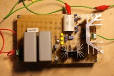
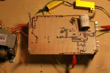
I've put together the higher voltage version with cascoded MJE350's based on the schematic from post #1750. It has been running for a couple of hours with an approximately 15k resistor load, Vin=366V, Vout=350V, Iccs=36.7mA.
I used R3=136k (2x68k in series), R4 and R5=78k (2x39k in series) and R8=4.7k. These resistor values are pretty much chosen based on what I had on hand 🙂. The pre-filter is CRC using 40uF MKP film caps and 390R resistor. On the scope I see Vin ripple is about 0.7Vpp, no ripple in output 😀.
So far looking good, now I'm off to build something to use this supply with 😀
Attachments
Oops! You had the numbers in your post! Sorry! 
Nice!
What is the DC input voltage? I see the substantial heatsink and was wondering what the total power dissipation across the IRF840.
I'll be making one for my preamp soon, as well.
Gary
Nice!
What is the DC input voltage? I see the substantial heatsink and was wondering what the total power dissipation across the IRF840.
I'll be making one for my preamp soon, as well.
Gary
:I've put together the higher voltage version with cascoded MJE350's based on the schematic from post #1750. It has been running for a couple of hours with an approximately 15k resistor load, Vin=366V, Vout=350V, Iccs=36.7mA.
I used R3=136k (2x68k in series), R4 and R5=78k (2x39k in series) and R8=4.7k. These resistor values are pretty much chosen based on what I had on hand 🙂. The pre-filter is CRC using 40uF MKP film caps and 390R resistor. On the scope I see Vin ripple is about 0.7Vpp, no ripple in output 😀.
So far looking good, now I'm off to build something to use this supply with 😀
Last edited:
So far looking good, now I'm off to build something to use this supply with 😀
The diy ultimate definition of vice versa?😀
Hi Salas,
I was wondering if you had any ideas about a 1-2 tube shunt regulator? MOSFETs are great but they need heat-sinks and can be killed, whereas tubes just sit there dissipating heat and are fairly tough - is there something with a GU50 as a shunt element perhaps - maybe with a 6N2P as a driver?
This would be a nice easy retro-fit to a tube amp with a little space on top and could also be wired point-point - avoiding PCBs (and heatsinks!)?
Sorry if this has been asked about before!
Could be done but bear in mind that their gm will be inferior and the output impedance will not be same league. You can transfer the simplistic regs topology to tubes version (4 tubes) if you got any suitable on hand fairly easy. It would need a reversion for the output since there are no N type vacuum elements of course. TO-220 Mosfets are very cheap to replace, if no accident victims they don't age, yes they need sinking, tubes need bases and occupy enough physical space too, can be relatively expensive, and higher gm ones have hungry heaters. Regarding the reference, 6n2p will be nowhere near the self noise of a Toshiba NOS JFET. There is nothing +sonically in tube regulators in my experience, semis do current better.
Thanks for the advice Salas, all noted. Is the tube still not suitable for a 450-500V (ish) shunt? I was thinking if one aimed for 20W peak dissipation you'd only have 22.5mA flowing, and GU50s can sit all day at 50mA.
I would be interested in a pure shunt TBH, just to pull down the rail a bit - if you see what I mean, so for 'quiet' stuff in the first 5 watts would be well regulated but it would not need to conduct for stuff above that as the power rail sag would all be from the output devices. More useful for class AB PP stuff I think, although I'd quite like to see if it made an SE sound better.
Maybe it wouldn't work very well - I don't know - it just seems a nice idea. I could be driven via solid state I guess..
You get most of the benefit by regulating the voltage stages in a power amp. Small power amps like most tube amps are VS solid state counterparts need the power stage sag to add some psychoacoustical ''oomph'' any way.
As far as I can see, with tube regulators there are few drawbacks without any benefit. The drawbacks are: extra power consumption for the regulator's tubes heaters, added space, added heat and higher Zo.
But compare the tube capacitance with that of the mosfet. You might not get the very low output impedance because of the lower gain, but it might be really flat out into the hundred kHz region if not more. 🙂 Another plus would be that tubes are more resilient to hick-ups. Of course, the power consumption would be quite a bit higher.
But compare the tube capacitance with that of the mosfet. You might not get the very low output impedance because of the lower gain, but it might be really flat out into the hundred kHz region if not more. 🙂 Another plus would be that tubes are more resilient to hick-ups. Of course, the power consumption would be quite a bit higher.
Nothing that an RF filter before the shunt regulator cannot do.
I just have to mention the original shunt regulators were tubes! Of course gas discharge tubes which come in fixed voltages and are by today's standards noisy. But I have seen tube shunt filters used with some success.
Of course tube shunt regulators can work quite well. The question in mind is: are they better than SS ones? It appears to me that SS ones are better in many ways. Anyhow, since it's about DIY, it's understood why people want to try various options and topologies.
I don't see any relation between an RF filter and what I was talking about.
I don't see the benefit of a shunt regulator having a flat response extended to hundreds of KHz.
- Home
- Amplifiers
- Power Supplies
- Simplistic mosFET HV Shunt Regs