Then these are the regulators I should use?
What about the update for the protection you made on the MOSFETs? Should I use it?
Yes, but you should scale down your R3 and R4 as I wrote, those are real HV example values shown. R3 15K 2W and R4 33K 1W should do for your 60V target. For R1, I don't know your current needs, but leave 25mA extra per reg on top of your max load demand. ICCS=(Vleds-Vgs)/R1. ~2V/R1 usually with green leds. No protection Zeners are needed at your voltage levels, delete them.
I hope this has not already been asked as I have tried to read through this thread and your NJFET Phono amp, have you tried replacing the led's with either an LM336-5 or LM 329DZ. If you have are they quieter and less temperature dependent than the led's.
Why don't work the HV shunt with this phono Puresound P10
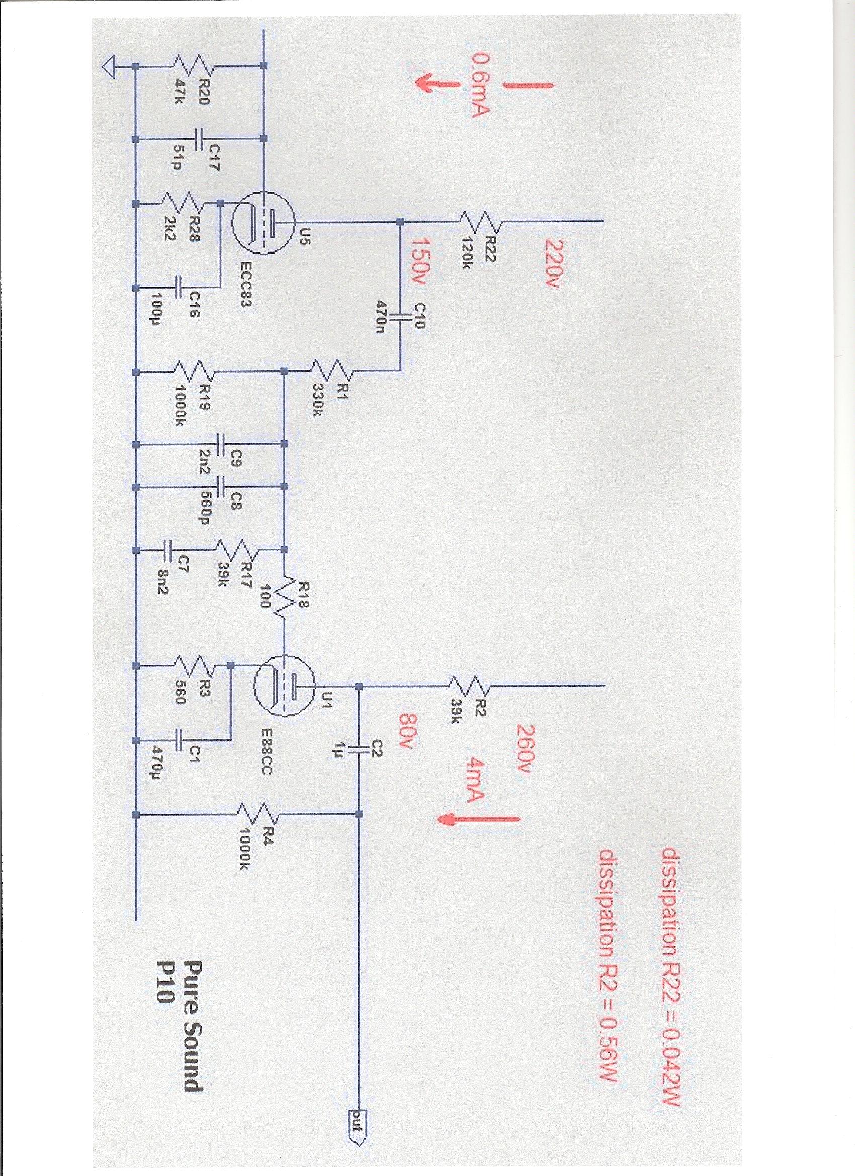
Just curious, the manufacturer said that works with tube shunt regulators
Thanks for help
Just curious, the manufacturer said that works with tube shunt regulators
Thanks for help
What do you mean it does not work with it? I see a normal common cathode with resistive anode load 2 stage circuit. Can't imagine what would exclude any regulator feeding it. Just assemble your circuit as it is drawn and use PSU voltage values exactly as written on it.

I used your schematic so I added 68K & 4.7uF instead 3.3uF to drop till 220V but the voltages measurements are:
CCS 260V both channels
ECC83
between 120K & 68K must be 220V and I have
L 206V
R 206V
between 120K & C10 must be 150V and I have
L 129V
R 133V
ECC88
between 39K & C2 must be 80V and I have
L 100V
R 102V
Of course I don't have sound so don't works.
N.B. post duplicated in Puresound P10 RIAA thread
CCS 260V both channels
ECC83
between 120K & 68K must be 220V and I have
L 206V
R 206V
between 120K & C10 must be 150V and I have
L 129V
R 133V
ECC88
between 39K & C2 must be 80V and I have
L 100V
R 102V
Of course I don't have sound so don't works.
N.B. post duplicated in Puresound P10 RIAA thread
did you wire that point to point?
measure your plate voltage, reading from plate to cathode....
measure your plate voltage, reading from plate to cathode....
Last edited:
Yes wired point to point, plate-cathode measurements:
ECC88
L 99V
R 101V
ECC83
L 139V
R 143V
Thanks for help
ECC88
L 99V
R 101V
ECC83
L 139V
R 143V
Thanks for help
your tube sections seems to be even.....you should have sound, maybe a break in connections somewhere...please recheck your wiring's and/or have someone look at your work, sometimes he will see soemthing you might have missed...
I used your schematic so I added 68K & 4.7uF instead 3.3uF to drop till 220V but the voltages measurements are:
CCS 260V both channels
ECC83
between 120K & 68K must be 220V and I have
L 206V
R 206V
between 120K & C10 must be 150V and I have
L 129V
R 133V
ECC88
between 39K & C2 must be 80V and I have
L 100V
R 102V
Of course I don't have sound so don't works.
N.B. post duplicated in Puresound P10 RIAA thread
Beyond that the noted currents are not exact, leading to different DC drops, biasing looks like working.
Sorry for my ignorance, wich pin heater is the positive & negative for ECC83 because original Puresound as soldered togheter pin 4 & 5 to one heater & pin 9 to the other heater, I mind positive heater is 4 & 5 togheter?
- Home
- Amplifiers
- Power Supplies
- Simplistic mosFET HV Shunt Regs