Wooooooooooow big, big upgrade, thanks Salas🙂
Very interesting 😀
Salas, did you have any concerns if i use a 1,5µF cap for C2?
Best,
Oliver
It will rise to Vo slower and can expose the fet to stress. Maybe its still OK though, I haven't used more than 1uF to say for sure.
Hi,Salas
My first shunt is working perfectly.Thanks for suggestions.The sound is not comparable to anything else in range from C-L-C, C-R-C or series mosfet psu.That is simply the music and everything else I tried euphony without dynamics and reality.The 12ax7 does not sound soft and restricted in treble like before anymore .
Now I need to build another one for that 12ax7 phono which now is shared with line amp psu and it consume around 2mA.Which current is desired to be set by R1.Phono is feed with over 1m of cable for a moment and the sound is fantastic.Now I imagine result with short cable so I must try it.
Is there any ccs current minimum regarding performance.I was thinking about 40mA or can I set it under 40?
memo:
If your consumption is 4-5mA for stereo, I would consider 30mA setting as lower ballpark. You would need 25mA for internal consumption and for keeping the output impedance as intended. Congratulations for your results. Its nice you like it. Is it a point to point build? Pictures are welcome.
If your consumption is 4-5mA for stereo, I would consider 30mA setting as lower ballpark. You would need 25mA for internal consumption and for keeping the output impedance as intended. Congratulations for your results. Its nice you like it. Is it a point to point build? Pictures are welcome.
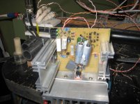
It is build on perforated board which can be rather called jungle liana to liana style but it sound marvelous so I go ahead the way it is.
I will post the photos when I will be able (camera problems).
Thanks for your beautiful device.
I will post the photos when I will be able (camera problems).
Thanks for your beautiful device.
memo:
If your consumption is 4-5mA for stereo, I would consider 30mA setting as lower ballpark. You would need 25mA for internal consumption and for keeping the output impedance as intended. Congratulations for your results. Its nice you like it. Is it a point to point build? Pictures are welcome.
Salas could I use this information for B+ tube 26 preamp?
Salas could I use this information for B+ tube 26 preamp?
Sure. Simply remember to allow 20-25mA spare in the reg after subtracting your max load draw from the total CCS setting.

Sure. Simply remember to allow 20-25mA spare in the reg after subtracting your max load draw from the total CCS setting.
HV settings for best performance.
Hi Salas.
I am sure this question has been answered many times before, but if I may: I want an output of 250V at a maximum of 16 m.a.. What would be the minimum voltage to input on the regulator to obtain optimun performances?
Would 35 m.a. be enough in the current department.
I read that bypassing C2 with a 100nf capacitor makes an interesting upgrade. Is there anything else we could do?
Thank you.
260-265V will suffice as minimum DC input to the 250V reg. 35mA will be enough for 16mA max load consumption. Make it 40mA if you can, its a bit better. CLC pre filtering and a good C2 or bypass, replacing the trimmer with a low ppm resistor after finding the value, a good C3 or bypass, a low ppm non inductive 120K Rref, short cabling to the load, that is about it.
260-265V will suffice as minimum DC input to the 250V reg. 35mA will be enough for 16mA max load consumption. Make it 40mA if you can, its a bit better. CLC pre filtering and a good C2 or bypass, replacing the trimmer with a low ppm resistor after finding the value, a good C3 or bypass, a low ppm non inductive 120K Rref, short cabling to the load, that is about it.
The 120K Rref must be 2W or can be 1W or less, I'm asking this info due to the fact it's very difficult to get 2W in only one resistor with low ppm....
2W or more. Many Volt across create dissipation. You can use 2x 220k-270k 1W in parallel. Arrange them in reverse direction between them. Like their color stripes or numbers & logo will look the opposite direction.
Dale RN70 in parallel wouldn't be bad also.
rather yes
200k-300k standard metal film (also RN Vishay) are quite inductive ( more the 10uH)
reverse parallel config will somehow reduce it but how much ??
best metal film tempoco for 2W resistors I have found 50ppm
MP 930 Caddock came to mine mind (noninductive -50ppm - but working voltage is a limit in HVSS 🙁
I found 120K 2W 50ppm metal film but I suspect is inductive
WELWYN|MFP2-120K JI|RESISTOR, 2W 5% 120K | Farnell España
WELWYN|MFP2-120K JI|RESISTOR, 2W 5% 120K | Farnell España
- Home
- Amplifiers
- Power Supplies
- Simplistic mosFET HV Shunt Regs