Better.
.model J201 NJF(Beta=1.621m Betatce=-.5 Rd=1 Rs=1 Lambda=2.236m Vto=-.6
+ Vtotc=-2.5m Is=114.5f Isr=1.091p N=1 Nr=2 Xti=3 Alpha=506.8u
+ Vk=251.7 Cgd=4.667p M=.2271 Pb=.5 Fc=.5 Cgs=2.992p Kf=604.2E-18
+ Af=1)
Shown below was the simulation using J201 for Q4 with no trimmer and R4 = 540k. It looks like it will take a very long time to settle at a intended Vout. Btw, I did try many different value for gate and base stopper as well as experimented with cascode driver stage posted earlier. None of them could prevent the Q3 from seeing excessive gate voltage, which was the root cause of all my previous MOSFETs failure. That was why I added TVS1 to protect Q3, and it has later proven to be a very effective protection. Since then, I got no more Q3 failure. However, using TVS1 did introduce some unexpected and interesting result. I shall elaborate on it later.
Thanks again for the Spice model and help.
Attachments
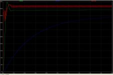
Using a J201 will end up with much smaller current through your voltage reference resistors and the capacitor there will take longer to "fill up".
Shown below was the simulation using J201 for Q4 with no trimmer and R4 = 540k. It looks like it will take a very long time to settle at a intended Vout. Btw, I did try many different value for gate and base stopper as well as experimented with cascode driver stage posted earlier. None of them could prevent the Q3 from seeing excessive gate voltage, which was the root cause of all my previous MOSFETs failure. That was why I added TVS1 to protect Q3, and it has later proven to be a very effective protection. Since then, I got no more Q3 failure. However, using TVS1 did introduce some unexpected and interesting result. I shall elaborate on it later.
Thanks again for the Spice model and help.
Limper with J201 as expected. You could use the 2 protective gate Zeners scheme during your experiments. But now your tweaks are mature anyway. There are no Q3 failures with the original SSHV BTW.
Limper with J201 as expected. You could use the 2 protective gate Zeners scheme during your experiments. But now your tweaks are mature anyway. There are no Q3 failures with the original SSHV BTW.
Yes, I totally agree with you on that because I have also used the low voltage version of your original design for other section in the same project, and they work fine. Therefore, my observation out of all these is that transient response of Vref stage need to match with that of the CCS stage. Using IXYS deivce will require changes to Vref circuit in order to isolate the transient influence of Vout.
Just got the new version up. It sounds pretty different from the first. Both are undoubtedly improvements. Really really good actually! It's clear that regarding the regulator as an adjunct to the audio circuit is a mistake. I need to repeat that to myself a few more times. I keep forgetting.
On the other hand, there are PS filter chokes before the output transformer and LC crossover after and I can't help wondering if with a greater knowledge of how they are interacting, it could be designed to sound as good without the shunt reg.
On the other hand, there are PS filter chokes before the output transformer and LC crossover after and I can't help wondering if with a greater knowledge of how they are interacting, it could be designed to sound as good without the shunt reg.
Attachments
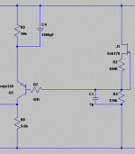
Why don't you just lift Vbe with a bypassed resistor if engulfing the FET in higher VDS is your goal, and keep a single common CCS? That example in the pic could give you 7-8V for instance. Saves you a great deal of headaches and its lower parts count.
That's a good idea. I shall seriously consider implementing it. Mmm... capacitor of such size may post substantial influence in term of overall sonic performance. I am wondering.

Can be 16V not to be bulky and bypassed by a small film cap. But it better be good on its own mainly. A Panasonic FM 1000uF/16 states 0.019 Ohm/100kHz Z and its 35V sibling 0.015 for instance. If you will test that Vbe lift idea, let us know.
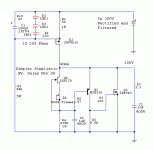
Latest build of Salas HVShunt Reg
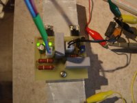
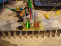
Thought I would share the newest Simplistic HV Shunt Regulator. The SSHVS will be used in a 12b4 preamp. It is set-up to provide 280V B+ on 300V input. The CCS regulates to 63mA. The 12b4 will be somewhere in the neighborhood of 20mA bias current.
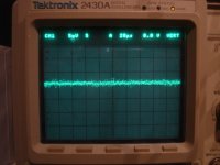
Attached is a picture of the scope on the output at 280V AC coupled. 5mV/div. No ripple observable. Also attached is the operating SSHVS on the test heatsink.
P.S. It will regulate down to 150V depending on setting of the pot.
Thought I would share the newest Simplistic HV Shunt Regulator. The SSHVS will be used in a 12b4 preamp. It is set-up to provide 280V B+ on 300V input. The CCS regulates to 63mA. The 12b4 will be somewhere in the neighborhood of 20mA bias current.
Attached is a picture of the scope on the output at 280V AC coupled. 5mV/div. No ripple observable. Also attached is the operating SSHVS on the test heatsink.
P.S. It will regulate down to 150V depending on setting of the pot.
Attachments
Last edited:
I am using a Kepco 400B power supply right now. For the preamp it will have a CLCRC filter ahead of it. I need to decide if I will use the gyrator or discrete ccs on the 12b4 before I take apart my old preamp and build the power supply.
Just use CLC. Avoid the RC if you can. Its nice you made it compact, keep the output cabling logical in the end build. Wishing success. Can you display the input line on the other scope's channel in comparison? Also how is the display at 5mV 20us with the reg off?
Will try but the PT is a little hot. The B+ cabling will be about 6 cm long to the gyrator or ccs.
Better keep it where is cooler and let be a little more away. So to avoid failures in the long run.
A few days ago I changed Q2 to MJE5731A . Sounds better. I'd like to understand why but looking at the data sheets I don't get it. Anyway, I think it's worth a try if you have them on hand.
- Home
- Amplifiers
- Power Supplies
- Simplistic mosFET HV Shunt Regs