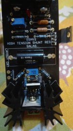
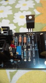
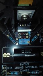
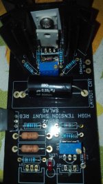
It does no have obvious RFI and it looks good. But do not go down only to 20mV vertical but to 1mS horizontal too. Always sweep high and low. And don't forget... in such occasions when looking for noises always use short ground tip.

Depending on the schematic - try to put a capacitor (around 1-2uF or more) to inputs of every stage, stage by stage beginning from the last stage, and listen to AC (look for by oscilloscope) the noise. It helps to determine the place of the problem.
sshv 2
Thank you very much for your help, Mr. Salas, it has helped me a lot.
Thanks also to your contribution poty.
I've located where the noise is coming from, sometimes focusing on internal problems and not looking at something around that might interfere.
The noise comes from the transformers of the preamplifier, although it is at a distance of 30cn below where the phono stage is installed. It captures the electromagnetic waves of this, I will install 0.5 mm thick mu-metal plates under the chassis of the phono stege if as in the top cover, I think that this would work out, I do not know another system to remedy this problem
You may put flux bands to the transformers themselves also
Stray Field - Custom Designed Toroidal Transformers from Nuvotem Talema
Stray Field - Custom Designed Toroidal Transformers from Nuvotem Talema
sshv 2
Flux bands in the transformed? I have never heard of that remedy, could you explain how to install these flux bars ?.
Thanks again.
You may put flux bands to the transformers themselves also
Stray Field - Custom Designed Toroidal Transformers from Nuvotem Talema
Flux bands in the transformed? I have never heard of that remedy, could you explain how to install these flux bars ?.
Thanks again.
Flux bands in the transformed? I have never heard of that remedy, could you explain how to install these flux bars ?.
Thanks again.
Simplest install is for a toroid. You dress a metal hoop around it like those on a barrel. Steel, copper, but mu-metal is the best. Thin works better.
An externally hosted image should be here but it was not working when we last tested it.
For EI type it is more shaped work:
Effective toroidal transformer shielding
The metal band forms an external shorted turn. So at the seam it must be conducting (no gap). Solder can be used there at the seam to stabilize the fit. You can also earth it for not collecting any possible electrostatic interference.
Commercial example of EI with copper band:
Vox AC15 Vintage Style Power Transformer, 100/120/220/230/240V
Vox AC15 Vintage Style Power Transformer, 100/120/220/230/240V
An externally hosted image should be here but it was not working when we last tested it.
Will it create a noisy groundloop if I have a common PSU supply for - let say - an input tube and a driver tube and use two SSHV's to regulate the B+ to each tube, and attach the negatives from the respective SSHV's to the local star grounds of each individual tube, and then from those ground nodes to chassis ground?
Or is it better to take the negatives from each SSHV to the common chassis ground point, and then make separate ground connections from there and to the local star grounds of each respective tube?
My head is spinning at the moment but the more I think about it the more I think that the last option is better. Any comments?
First option, narrower loop area. i.e. better (less susceptible to interference). Provided you use twisted pair rails cabling also.
Hi everyone
a few weeks ago I can not make these cards work (those of Salas HV shunt).
For twice the resistance R1 is always burnt but I can not understand where I may have failed.
as soon as I can publish the photos of the cards
Would you have advice to give me?
a few weeks ago I can not make these cards work (those of Salas HV shunt).
For twice the resistance R1 is always burnt but I can not understand where I may have failed.
as soon as I can publish the photos of the cards
Would you have advice to give me?
Hi everyone
a few weeks ago I can not make these cards work (those of Salas HV shunt).
For twice the resistance R1 is always burnt but I can not understand where I may have failed.
as soon as I can publish the photos of the cards
Would you have advice to give me?
Burned R1 usually tells there is at least a burned Q1 too. What were the conditions? Info is needed to evaluate causes. In post #1 there is also a link on how to safely troubleshoot and repair the reg itself.
hi all, since it is not easy to find the jfet 2sk117gr is it possible to replace this with the jfet 2sk170bl?
I'm afraid I received a scam from China where I bought the jfet 2sk117gr
I'm afraid I received a scam from China where I bought the jfet 2sk117gr
Yes you can, it can be more sensitive to temperature drift because of more transcoductance, but quality will be as good.
- Home
- Amplifiers
- Power Supplies
- Simplistic mosFET HV Shunt Regs
