Both gave their magic smoke up. They are fixed and working perfectly now. I will drop the current down a little later. I want to have room to experiments with bias points.
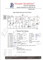
Merlin, I suspect that you LED's have too much voltage drop. I see in your photo's that you have new type LEDs like I tried. Had almost 8.5V drop accross three of them which made the sense resistor R1 heat up too much and burn out. Please measure them. You only need about 6V of drop.
And with you blowing the gate resistor your symptoms are exactly as mine with too big drop across the LED's.
Merlin. Put a resistor with a value between 500R and 1k in series with the LED's and measure the voltage drop accros the LED's with the 9V battery hooked up.
1K 5.48V, thanks Gregory.
Both gave their magic smoke up. They are fixed and working perfectly now. I will drop the current down a little later. I want to have room to experiments with bias points.
You fixed so fast? When was the accident?
IRFP
I don't have on hand, I have Mike IRF9610 Vishay or the others I posted?
1K 5.48V, thanks Gregory.
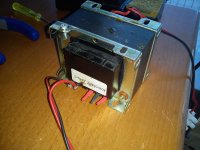
Something beyond the circuit itself must be happening. Do something drastic. Get rid of the peripherals. Use a simple small transformer, bridge with 1000V piv diodes, one 100-150uf capacitor, short Vin wires, and feed. Simple grounding, use no crocodile clips. Maybe a transient discharge from the big PSU & filter hits whatever you try out now. Something that the CCS can't hold up to... Can't think of what for sure, this is baffling me, and is only hands on to really tell.
I don't have on hand, I have Mike IRF9610 Vishay or the others I posted?
Those are good parts, but I am afraid this is not the real problem.
Salas, is spot on with his recomendation. With that current level much better using dual mono and big heat sinks. My SSHV regs live on these sinks. 1 reg per sink passing 70mA total current with 345V Input. 310V output. Load is 30mA.
The heatsinks stay comfortable warm but are warm non the less. ABout 45-50C in 28C room
Isn't winter in the USA? Can you survive with 28C in the room?

In that case, I would make another one the same reg for double mono both with 47R R1, because with your construction space and sinks, if you will crank the CCS to 70-75mA (extra to 50mA load is for the reg to work well) I don't see it will hold thermally well.
Thanks Salas, I will wait for the GB and make 2 SSHV2 instead of built another SSHV1. Wish you and all DIYaudio members a happy new year.
Something beyond the circuit itself must be happening. Do something drastic. Get rid of the peripherals. Use a simple small transformer, bridge with 1000V piv diodes, one 100-150uf capacitor, short Vin wires, and feed. Simple grounding, use no crocodile clips. Maybe a transient discharge from the big PSU & filter hits whatever you try out now. Something that the CCS can't hold up to... Can't think of what for sure, this is baffling me, and is only hands on to really tell.
Those are good parts, but I am afraid this is not the real problem.
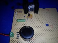
OK I use with the ne P2P CCS a 150uF mains filter cap 4 x UF4007 diodes & the old tx to see what happens.
Thanks Salas, I will wait for the GB and make 2 SSHV2 instead of built another SSHV1. Wish you and all DIYaudio members a happy new year.
Maybe you have a 10-15mA application for the nice small one you built? Its a nice looking board. Happy new year to you and to everybody.🙂
Also burned 220R gate resistor & IRF9610 supplied by Mike😡
Vin reg 330V measured at the main filter cap
Vin reg 330V measured at the main filter cap
Attachments
Last edited:
I don't have on hand, I have Mike IRF9610 Vishay or the others I posted?
IRFP
I get one IRFP9240, coul I try with the new tx & psu?
Also burned 220R gate resistor & IRF9610 supplied by Mike😡
Vin reg 330V measured at the main filter cap
Merlin
Do you keep the Drain of you 9610 open?
Merlin
Do you keep the Drain of you 9610 open?
Yes, nothing connected.
Yes, nothing connected.
Excuse me for a silly question, that means the middle pin connect to nothing
Phelipe,
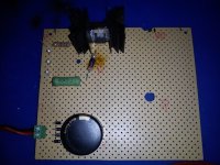
check your connections one more time.
I think that the 56k should connect with the leds and 220R at one point together.
check your connections one more time.
I think that the 56k should connect with the leds and 220R at one point together.
Phelipe,
check your connections one more time.
I think that the 56k should connect with the leds and 220R at one point together.
yes, look like your 220ohm connected to ground at one end.
Phelipe,
check your connections one more time.
I think that the 56k should connect with the leds and 220R at one point together.
quanghao schematic connect the LEDs between 220R gate resistor & 56K that isn't correct?
Attachments
- Home
- Amplifiers
- Power Supplies
- Simplistic mosFET HV Shunt Regs