5v 2a switching power supply , are a good option for each filament of 300B ?
Only if it has an isolated output, and is very quiet (not likely).
Using a switching supply around here is blasphemy 😀 They work very well actually and don't generate much noise or heat. Nearly all have isolated outputs good for 1500v or so. The 7805 regulators are ancient technology now. Check out the L4940 with only 450mV of voltage drop.
Easiest 5 volt supply 4 lithium ion batteries in series!
For a 1.2A filament, four batteries per channel, really?
Last edited:
For a 1.2A filament, four batteries per channel, really?
I think he said it in a joke
I always refer to the Sakuma amps for something like this. 300B / VV300B push-pull end power amplifier is an example. A diode FW with CRC using big caps.
How about "the sound"?This is easy, cost effective, and works for two 300B tubes: RS-15-5 MEAN WELL | Mouser Schweiz
This is full wave rectification using four diodes.I always refer to the Sakuma amps for something like this. 300B / VV300B push-pull end power amplifier is an example. A diode FW with CRC using big caps.
It works fine.
I really hope you're kidding. Lithium-ion cells put out 4.2 volts each when fully charged. Four in series put out 16.8 volts, and will instantly fry the filament of that overpriced 300B tube, destroying it for good.Easiest 5 volt supply 4 lithium ion batteries in series!
Did you mean four NiMH cells? 1.2 volts each, 4.8 volts for all four.
The most logical solution to the original engineering problem is to use any of the thousands of cheap 5V USB chargers that are everywhere these days; you probably have several lying around your house. Cut off the microUSB or miniUSB plug, and there's your clean, regulated, +5V DC. Not quite as clean as four NiMH cells in series, but a heck of a lot more practical.
-Gnobuddy
How about "the sound"?
Oh, I don't hear any sound at all from my SMPS 😀
Ok, ok, some say SMPS are bad, because they introduce high-frequency switching noise to the system. This may have been a real issue with earlier designs. I am using a bunch of current MeanWell SMPS as main PSUs for my Aleph single ended amp. It sounds very good.
When I looked at the DC output using my scope, there was VERY little noise (at a steady 5 amps!). After a very simple CRC filter the DC rails looked the same as with the scope probes shortened to each other.
But yes, using a SMPS for a 300B amp may be considered blasphemy. But the question was about "the simplest filament supply", not about religious or similar beliefs. The SMPS was my answer to the "simple" question. It's not only simple, but also good. I am not saying it's the only solution.
Could this help to flatten the ripple for the 5v filament supply ?
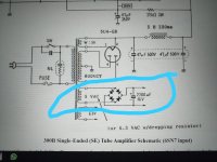
Yes, with a 5V winding you can use a chassis mount 25A bridge rectifier and a cap as a cheap DC supply. The chassis mount rectifiers tend to be kind of lossy, which helps bring the output voltage back down towards 5V after rectification. The capacitor there takes an absolute beating, so at minimum use PSUD to determine how much ripple current that cap has to deal with, then purchase parts accordingly.
It really, really doesn't work fine. 🙁 It worked badly in 1970, but back then, it was the only option.This is full wave rectification using four diodes.
It works fine.
Fifty years later, it is an incredibly poor choice. A 5V SMPS is vastly superior.
Let's talk details. The problem with the old primitive circuit is simple: a 300B draws 1.2 amperes of filament current. When you draw current from a simple four-diode bridge rectifier + filter cap, the voltage immediately develops ripple - it fluctuates at twice the frequency of the AC, i.e. 100 Hz or 120 Hz depending on whether you have 50 Hz or 60 Hz AC mains in your country.
1.2 amps of filament current is a lot. It would take an absolutely enormous filter capacitor to smooth out the ripple - 2200 uF doesn't even come close to being adequate.
So far I've just used words, so how do you know I'm not ignorant or full of it? Let's look at some engineering reality.
The first attached image shows the suggested circuit; a 5V RMS transformer winding feeding a diode bridge, with a 2200 uF filter cap to smooth the resulting "dirty DC".
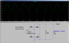
The second attached image shows an LTSpice simulation of the circuit. LTSpice is a circuit simulation program with a long history going back decades. It originated as a research project created by a genius at Berkeley university, and has been steadily refined and updated since then. For simple circuits like this one, LTSpice simulations are quite accurate.
Note that 5V RMS is 7.0711 volts peak; LTSpice uses peak voltage, not RMS, so you'll see that I've set up a 60 Hz voltage generator with a peak voltage of 7.0711 volts in the simulation. This represents the 5V RMS transformer winding.
As you can see from the simulation, a diode bridge and 2200uF filter cap produces absolutely horrible "DC". There is an enormous amount of ripple - more than 2 volts peak to peak - which is more than 40% of the nominal 5V DC!
40% ripple voltage is atrocious - so bad that it shouldn't be considered acceptable for an instant. It isn't even reasonable to call this DC; it's halfway between being DC and AC. It's garbage.
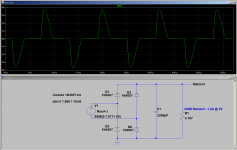
You can't just solve the ripple problem by stuffing ridiculous amounts of capacitance into the circuit, either. The bigger the filter capacitor, the bigger the peak currents flowing through the diodes and the transformer. These huge current peaks radiate electrical noise, and even corrupt the waveforms on all the other transformer windings, because of their effect on the shared transformer core.
The third attached image shows the current flowing out of the 5V transformer winding, going into the diodes. Note the current peaks of nearly +/- 4 amps, and the sharp, spiky waveform. This sort of waveform has a lot of harmonics, and as a result, radiates noise not only all the way through the audio band, but even into the radio frequency bands.
In a nutshell, the 1970s solution to feeding DC to a 300B filament (i.e. a 5V transformer winding at 60 or 50 Hz, diode bridge, big filter cap) is terrible. It's awful. Anyone who uses it should be embarrassed!
So what's a better solution? In 1970, you designed the power supply to produce 10 volts DC with 40% ripple, so that it never dipped below 5V at any instant. Then you added a big power transistor and a huge heat sink to drop that "dirty DC" down to a clean 5 V DC. You might even need a cooling fan for the heatsink. This solution is huge, hot, heavy, expensive, and incredibly inefficient, but that was the only option decades ago.
Luckily for us, clever electronics engineers have been hard at work for fifty years since 1970, electronics technology has evolved a lot, and now we have an absolutely wonderful solution: use one of the dirt-cheap 5V USB chargers or SMPS rated for 2 amps or more. Ripple is far lower than you get from the 60 Hz diode bridge + filter cap. What little ripple there is, is at a high frequency of tens or hundreds of kilohertz, which makes it easy to filter out with a relatively small RC filter if you really need to.
-Gnobuddy
Attachments


I've been using small SMPS for heater power in my (guitar) tube amps for some years now, and this is exactly my experience as well.When I looked at the DC output using my scope, there was VERY little noise (at a steady 5 amps!). After a very simple CRC filter the DC rails looked the same as with the scope probes shortened to each other.
Meantime, the ancient-technology circuit being suggested here (bridge rectifier at 60 Hz, 2200 uF filter cap) produces an unbelievably poor 2 volts peak-to-peak of ripple - that's 40% ripple - at 60 Hz, and even worse at 50 Hz), as shown in the simulation pics I attached to my previous post. 😱
The reality is simple: the classic diode bridge + capacitor DC power supply has the pants beaten off it by a modern SMPS in every way. The old classic circuit is at its worst when you need a lot of current at a low voltage; and that's exactly the case in this particular application, where we need 1.2 amps of clean DC current at only 5 volts DC.
The old classic circuit isn't quite as bad when we want 350 volts at 100 mA (i.e. lots of volts and little current) for a tube guitar amp, and there are few off-the-shelf 350V DC 50W SMPS modules available, so the diodes + capacitor approach still makes sense for powering the anodes of the valves. But the heaters? An SMPS is a far better solution.
That's exactly the problem. The 300B is an object of worship to some....religious...beliefs...
I agree 100%. Not just good, it's the obvious best engineering solution....The SMPS...not only simple, but also good.
-Gnobuddy
You're also selling the choke input filter pretty well, but of course this requires the 6.3V winding.
OK , so is an SMPS 5VCC power supply a good choice, even if some kind of noise is generated ?
Mean Well RS-15-5 is a good quality option in this case.
Mean Well RS-15-5 is a good quality option in this case.
Be careful with the SMPS. If you are using a cathode biased amp, several of those SMPS have V- attached to the case of the SMPS. If you want to use a SMPS like this, then you're going to want to employ fixed bias to get around that or do some research on what the possible negative consequences could be to having the SMPS case biased up above ground.
Agreed, vastly better than only a filter cap....choke input filter...
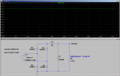
But of course you need a huge, heavy, expensive choke that can handle 1.2 amps continuous current, has low DC resistance, and has tons of inductance.
A simulation with a 1-henry choke and 2200uF filter cap suggests you need 11 volt peaks from the transformer (nearly 8 volts RMS) to get 5 volts out of the LC filter. It's a very nicely filtered 5 volts DC, though. 🙂
-Gnobuddy
Attachments
Generally, in my experience, yes. Certainly much better than the four diodes + 2200 uF circuit, which is quite useless for this particular application.OK , so is an SMPS 5VCC power supply a good choice, even if some kind of noise is generated ?
You can also use a 6V DC SMPS, add a 0.82 ohms series resistor (rated 3 watts or more), and use something like a 1000 uF electrolytic cap in parallel with something like a 1 uF film or ceramic cap to remove any remaining ripple. The resistor will drop the extra volt, so the filament gets 5 volts (assuming it draws 1.2 amps as the datasheet specifies.)
-Gnobuddy
The SMPS I've used invariably have plastic cases. The ones that have two-wire AC cords (or 2 prongs that plug into the AC outlet) always seem to have the output floating....several of those SMPS have V- attached to the case of the SMPS...
Using an ohmmeter, check for continuity between the output DC terminals of the SMPS and the incoming AC terminals. If you measure no continuity, the DC output is floating with respect to the incoming AC.
(In many cases, two small-value capacitors are used to float the DC output halfway between ground and 120 VAC. Connect something lower impedance from the DC output to your circuit, and you override this.)
-Gnobuddy
- Home
- Amplifiers
- Tubes / Valves
- Simplest or easyest dc filament supply for 300B