The problem I've noticed with many of the delay circuits I've found online is the inability of the circuit to self-reset. Using a simple RC network is fine for adjusting the time but the circuit needs a way to reset itself once power is removed. You don't want blackouts power cycling your amp without the time delay being reset quickly.
I've seen many time-delay circuits using *complicated* op-amps and darlington transistors but nothing seemed simple enough to just whip one together with spare parts.
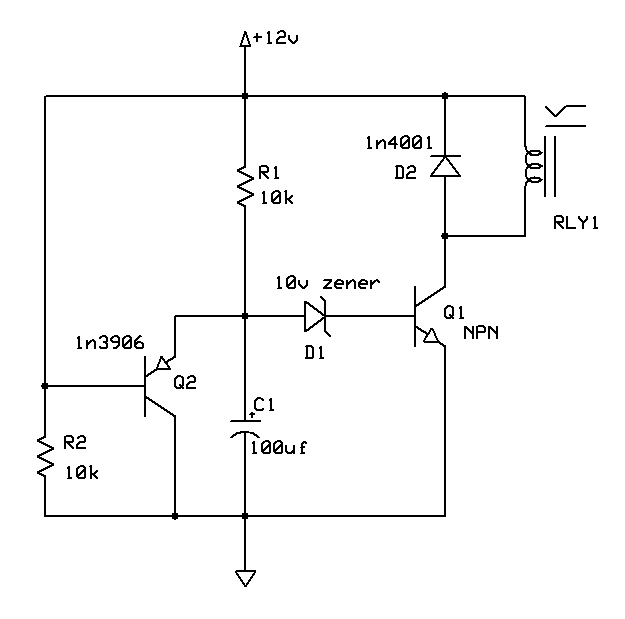
It's pretty self-explanatory for those who understand transistors. For those who don't, I'll give a brief explanation.
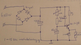
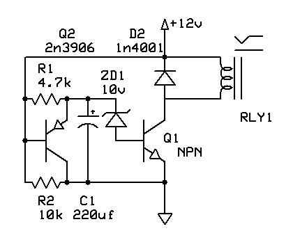
When powered on: 12v is applied to Q2's base causing it to turn off and allow C1 to charge via. R1. C1 charges until the breakdown voltage of D1 (10v) is reached at which point Q1 conducts and closes RLY1.
When powered off: RLY1 opens. The energy stored in C1 will flow through Q2 through it's base and R2 to ground causing Q2 to conduct and discharge C1. That is how the circuit resets C1 to a discharged state of .5~.6v or so. I'd have to check data on Q2 to tell you that exact number.
Remember to choose R1 to supply enough base current to Q1 based on your choice of transistor. A high gain transistor will give you more flexibility of R1's value giving you a little finer adjustment of time. Then calculate C1 to adjust delay time and adjust R1 to fine tune it.
Feel free to improve on the design. Thinking about it, Q1 should be a mosfet and D1's value lowered.
I've seen many time-delay circuits using *complicated* op-amps and darlington transistors but nothing seemed simple enough to just whip one together with spare parts.
It's pretty self-explanatory for those who understand transistors. For those who don't, I'll give a brief explanation.
When powered on: 12v is applied to Q2's base causing it to turn off and allow C1 to charge via. R1. C1 charges until the breakdown voltage of D1 (10v) is reached at which point Q1 conducts and closes RLY1.
When powered off: RLY1 opens. The energy stored in C1 will flow through Q2 through it's base and R2 to ground causing Q2 to conduct and discharge C1. That is how the circuit resets C1 to a discharged state of .5~.6v or so. I'd have to check data on Q2 to tell you that exact number.
Remember to choose R1 to supply enough base current to Q1 based on your choice of transistor. A high gain transistor will give you more flexibility of R1's value giving you a little finer adjustment of time. Then calculate C1 to adjust delay time and adjust R1 to fine tune it.
Feel free to improve on the design. Thinking about it, Q1 should be a mosfet and D1's value lowered.
Attachments

Last edited:
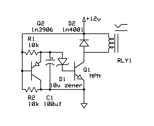
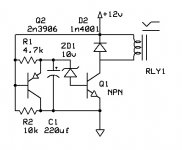
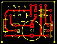
Here's a slightly more "PCB layout friendly" version.
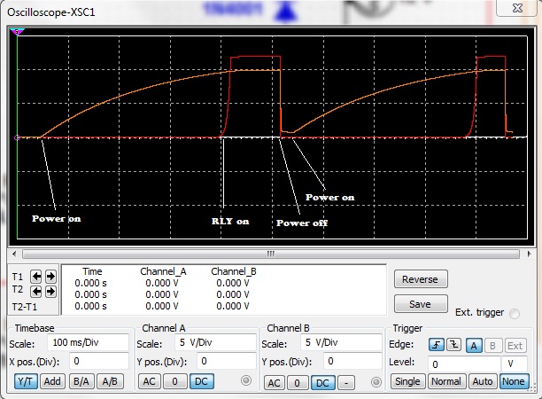
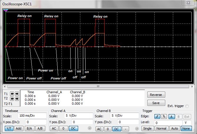
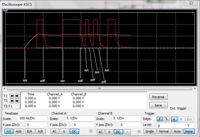
Below you can see the charge of C1 in orange, and the relay in red. When power is turned off, note the fall time on C1. When power was quickly turned back on, the charge begins again essentially from zero.
Below you can see the charge of C1 in orange, and the relay in red. When power is turned off, note the fall time on C1. When power was quickly turned back on, the charge begins again essentially from zero.
Attachments

Last edited:
Here's how I see it...
Q2 is simply being used as a diode across R1 via its B and E junction. You could just fit a 1N4148 across R1 and discard Q2 and R2.
The zener appears to be the wrong way around. As it stands it conducts when the voltage across C1 goes over around 0.7 volts.
Leaving the base of Q1 "floating" which the diode does may not be best practice and certainly is a FET were used it wouldn't work for that reason. A FET would have a turn on voltage (Vgs) of around 4 volts or so and may allow the zener to be dispensed with.
I agree that quick resetting is an area where many designs fall down.
http://www.diyaudio.com/forums/solid-state/224957-simple-universal-speaker-delay-using-triac.html
Edit... the above should read "As it stands it conducts when the voltage across C1 goes over around 0.7 volts PLUS vbe of Q1"
Last edited:
Given that the timing capacitor is 100uF (or whatever on has in the junk box) I would put a small resistor in series with the collector of the transistor Q1 (maybe 100R or so). This will limit any peak discharge current to a safe value in the event that the 12v rail collapses quickly. (A slow collapse on the 12v would turn on the transistor slowly and thus a high discharge current is unlikely.)
And shouldn't that be a 2N3906 (not 1N3906 which is a high current diode....) ? (although any equivalent device would work equally well)
And shouldn't that be a 2N3906 (not 1N3906 which is a high current diode....) ? (although any equivalent device would work equally well)
Last edited:
Sorry about that. 2n3906 is the correct number for Q2. I will fix that. The zener is also backwards. Who drew this thing!
Mooly, the 1N4148 would let C1 discharge into the relay correct? Until Q1 opens? Replaced Q2 with 4148. Capacitor does not discharge quickly.
sevenup, What's 3g?
Mooly, the 1N4148 would let C1 discharge into the relay correct? Until Q1 opens? Replaced Q2 with 4148. Capacitor does not discharge quickly.
sevenup, What's 3g?
Last edited:
Who are the admins and mods for this forum? I need to be able to edit my posts to correct things like mistakes ESPICIALLY in schematics.
It's too easy to overlook an error and potentially dangerous to those who attempt to build a schematic without reading the whole thread where an error may have been pointed out.
$.02
Here's the update. ZD1 = 1N4740
It's too easy to overlook an error and potentially dangerous to those who attempt to build a schematic without reading the whole thread where an error may have been pointed out.
$.02
Here's the update. ZD1 = 1N4740
Attachments
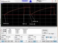
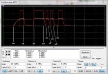
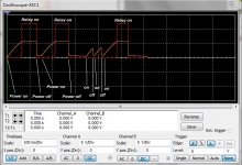
Here's a couple screen shots of the circuit using Q2 and the one below it just using a diode in place of Q2 (as per sevenup2278's schematic). There is no control of the discharge of C1. Momentary loss of power will not "reset" C1 to a discharged state. You can see in the second image how the capacitor charge (in orange) does not decrease or "reset" when the unit is powered off.
Attachments
It appears that one end of resistor R2 is connected to the +12V supply, and the other end of R2 is connected to the +0V supply, also called "ground". What function does R2 perform?
It appears that one end of resistor R2 is connected to the +12V supply, and the other end of R2 is connected to the +0V supply, also called "ground". What function does R2 perform?
When the circuit is off, R2 gives Q2's base a path to ground causing Q2 to conduct and discharge C1 (when C1 has a charge). When the circuit is powered, Q2's base sees 12v which keeps the transistor off allowing R1 to charge C1.
I've adapted this circuit from an electric vehicle DC motor controller I designed years back. I used it as a throttle buffer so when you stomped the throttle to the floor, the motor would receive a slow rise in voltage to avoid jerky starts. When the throttle is released, the controller had to reduce the voltage as quickly as the throttle was released.
Last edited:
I can't quite tell from your screen caps, what duration delay does this circuit give as drawn?
If it works well this is exactly the sort of delay circuit I've been looking for!
If it works well this is exactly the sort of delay circuit I've been looking for!
I can't quite tell from your screen caps, what duration delay does this circuit give as drawn?
If it works well this is exactly the sort of delay circuit I've been looking for!
In which circuit you mean ? 😕
You will have to calculate values based on the components you use.
First choose Q1 with enough current to low-side switch your relay.
Then choose a value for R1 that provides enough current to drive to Q1's base.
Choose a value for C1 to adjust time. Larger = longer.
Benchtest the circuit.
First choose Q1 with enough current to low-side switch your relay.
Then choose a value for R1 that provides enough current to drive to Q1's base.
Choose a value for C1 to adjust time. Larger = longer.
Benchtest the circuit.
Hi,
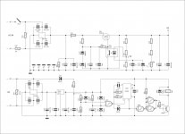
I know that people get scared when somebody recommended to use a micro as a control in an amplifier. To show you how easy it is attached is a schematic showing the circuit using a Micro Nano 8 that will do what your are trying to do with few components and also the program to control the relay. You can add other options but that it is another talking. I called the basic Micro Nano 8 a programmable LM555. It is does everything with no components. You can program all the 4 pins to control 4 relays. Also you can program the pins output high to low,low to high, generate pulses, pwm and sine waves.
I am trying to encourage all members of the Diyaudio to start using micro in their design but up to now I am losing the battle. Once you do one you will never go back. I think this is good project for a micro.
Attachments
I hate microcontrollers. No offence. Even my 144kw motor controller uses analog electronics.
I built the circuit and it works as designed. R1=10k and C1=2200uf. About ~20sec delay. I'm using a 2n3904 as Q1 and a 2n3906 as Q2. I only had 9.1v zeners for testing. Using a 10v zener as shown in the schematic will add another second or two.
C1 takes up a bit of real estate (I like small layouts) but it does the job.
Ok, let me dust off my high school physics memories and tell me if I did this right.
I happen to have a 2N5210 transistor on hand, according to it's datasheet it has a collector current of 100mA, and a collector cut-off current (Icbo) of 50nA.
So if R=V/I the max R1 I could have at 12v would be 240M? [12/0.00000005]
So far so good?
So based on the max R1 value and C1 of 220uf, i get a time constant of 880 minutes at 12v.
Using 10K, I get 2.2s. I've got a whole ton of 22k resistors on hand, those give me a time constant of 4.84s. how do I go from RC to the delay time?
I also have an appropriate relay with a coil current of ~40ma, so my 100ma collector current Q should be fine?
And if I wanted to adapt this circuit for use with 18v, for say a chip amp soft start, I would raise the zenner voltage to around 16v? Also for a DIYer who doesn't have a bunch of resistors on hand, and would be ordering parts specifically for this project, R1 would be better replaced with a 25k, or 50k pot wouldn't it? Also the biggest problem with going from calculated values to a working circuit would be the tolerance of C1, a 20% variance gives +/- ~1 s to RC.
For anyone else considering this circuit, digikey prices it out as less than $1.50 + relay (probably about $2-$3).
- Status
- Not open for further replies.
- Home
- Amplifiers
- Tubes / Valves
- Simple Time Delay (no more excuses for not having one)