I've felt a 555 timer was overkill for delay circuits likes these as well, this circuit is wonderfully simple and cheap.
RC for 10k, and 2200uf is 22s, so delay would be just less that 1 RC. I'm sure you can work it out more precisely based on the charging current of C1, the current over R1 and the zenner voltage but the formula is beyond my tired and out of practice mind at the moment.
RC for 10k, and 2200uf is 22s, so delay would be just less that 1 RC. I'm sure you can work it out more precisely based on the charging current of C1, the current over R1 and the zenner voltage but the formula is beyond my tired and out of practice mind at the moment.
Try one of these. I use them.
32091 Mars Solid State Delay on Make Timer Relay | eBay
You might be able to get one elsewhere, Grainger?
I have found that if the relay controlled by this timer does not provide enough load on the relay you might have to series a resistor to increase the loading to make it work properly. Minimum load is 40ma.
Ok, let me dust off my high school physics memories and tell me if I did this right.
I happen to have a 2N5210 transistor on hand, according to it's datasheet it has a collector current of 100mA, and a collector cut-off current (Icbo) of 50nA.
So if R=V/I the max R1 I could have at 12v would be 240M? [12/0.00000005]
So far so good?
So based on the max R1 value and C1 of 220uf, i get a time constant of 880 minutes at 12v.
Using 10K, I get 2.2s. I've got a whole ton of 22k resistors on hand, those give me a time constant of 4.84s. how do I go from RC to the delay time?
I also have an appropriate relay with a coil current of ~40ma, so my 100ma collector current Q should be fine?
And if I wanted to adapt this circuit for use with 18v, for say a chip amp soft start, I would raise the zenner voltage to around 16v? Also for a DIYer who doesn't have a bunch of resistors on hand, and would be ordering parts specifically for this project, R1 would be better replaced with a 25k, or 50k pot wouldn't it? Also the biggest problem with going from calculated values to a working circuit would be the tolerance of C1, a 20% variance gives +/- ~1 s to RC.
For anyone else considering this circuit, digikey prices it out as less than $1.50 + relay (probably about $2-$3).
I'm not good with math. The second (pun intended) time becomes a variable, I throw in the towel.
Calculate RC until the charge on C equals your zener's breakdown voltage. That gets you in the ballpark. There are ways to calculate how much higher then zener it needs to be to to produce the required current on Q1's base but that's beyond me. Zener+Vbe-Vce? If Q1 is high gain then R1 could be a high value allowing you to reduce the size of C1.
The "magic" in this circuit is it's simplicity and cost but also how Q2 is implemented to reset the timer.
Can't you soft-start a chip amp with just RC on the mute input?
Try one of these. I use them.
32091 Mars Solid State Delay on Make Timer Relay | eBay
You might be able to get one elsewhere, Grainger?
I have found that if the relay controlled by this timer does not provide enough load on the relay you might have to series a resistor to increase the loading to make it work properly. Minimum load is 40ma.
That price is reasonable but the circuit posted is less then $.50 in parts which most tinkerers have laying about with the exception of the zener diode. Multiple zeners could probably be used. I just happen to have a wide variety available including some odd-balls.
Last edited:
When the circuit is off, R2 gives Q2's base a path to ground causing Q2 to conduct and discharge C1 (when C1 has a charge). When the circuit is powered, Q2's base sees 12v which keeps the transistor off allowing R1 to charge C1.
It looks like a neat circuit, with the big merit of being very simple.
Concerning the question about the role of R2, then whether it serves a purpose or not presumably depends on the nature of the 12V supply, and how it behaves in the event that the power goes off. I think your answer above is given under the assumption that one simply disconnects the 12V supply? But that might well not really be the actual "failure mode" in the event of a power failure.
For example, if the 12V was also serving the purpose of providing a smoothed DC heater supply for some of the tubes, then R2 would play no role, since it would merely be in parallel with the much lower resistance of the tube heaters.
The bottom line, presumably, is that the recovery time of your delay circuit is determined roughly by the RC time constant of the 12V supply, where C is the value of its smoothing capacitor and R is the resistance of its load. R2 in your circuit is in parallel with whatever other load resistance is present, and so whether it has a significant effect depends on the comparitive values of the two. But since the 12V supply is, at the very least, required to supply the actuating current for the relay, it seems unlikely that R2 of 10Kohms will play a very significant role in reducing the RC time constant of the 12V supply.
Chris
Last edited:
Have any of you "designers" taken into account the variable mains voltage that will be supplied to your equipment?
The delay must work reliably at all mains voltages.
In the UK, this would be 226Vac to 254Vac.
The lower 216Vac of the harmonised EU supplies does not occur as "normal" operation in the UK.
If your transformer is fed with minimum voltage and with maximum voltage, the output of the transformer will change !!!!!!
The delay circuit MUST work reliably over the full range of secondary voltages that can and will occur as a result of our Mains Voltage tolerances.
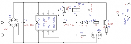
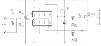
If reliability is important, the 555 would be a good choice. And it can drive LEDs too.
Something like this:
edit: the first schematic is for a dual color common cathode LED. One can of course drop the LED circuits if not needed.
edit2: in the first schematic, the pin 4 should go to Vcc, like in the second. Sorry.
Something like this:
edit: the first schematic is for a dual color common cathode LED. One can of course drop the LED circuits if not needed.
edit2: in the first schematic, the pin 4 should go to Vcc, like in the second. Sorry.
Attachments
Last edited:
Hi,
I know that people get scared when somebody recommended to use a micro as a control in an amplifier. To show you how easy it is attached is a schematic showing the circuit using a Micro Nano 8 that will do what your are trying to do with few components and also the program to control the relay. You can add other options but that it is another talking. I called the basic Micro Nano 8 a programmable LM555. It is does everything with no components. You can program all the 4 pins to control 4 relays. Also you can program the pins output high to low,low to high, generate pulses, pwm and sine waves.
I am trying to encourage all members of the Diyaudio to start using micro in their design but up to now I am losing the battle. Once you do one you will never go back. I think this is good project for a micro.
I too am a fan of the micro controller. The pic 12F683 (8 pin) adds an A/D converter to monitor current to the mix as well as being able to turn things on and off. It costs a staggering $2.
Yes, I started using microcontrollers too, especially to keep an eye on currents and turn things off.
It's too convenient not to use it.
It's too convenient not to use it.
I forgot something very important...
WARNING: you can't just use a delay in *any* amplifier! Weird things can happen at a sudden turn on. For example, current peaks can occur in the power tubes, because some capacitors are empty and need a few time constants to charge up.
And if the bias is fixed, it must be present before applying full HV.
It is best to use a vacuum rectifier because of its soft, progressive start. For the delay, just put a relay in its heater circuit.
A mosfet with a R-C delay in its gate will give a soft, controllable start, too.
It looks like a neat circuit, with the big merit of being very simple.
Concerning the question about the role of R2, then whether it serves a purpose or not presumably depends on the nature of the 12V supply, and how it behaves in the event that the power goes off. I think your answer above is given under the assumption that one simply disconnects the 12V supply? But that might well not really be the actual "failure mode" in the event of a power failure.
For example, if the 12V was also serving the purpose of providing a smoothed DC heater supply for some of the tubes, then R2 would play no role, since it would merely be in parallel with the much lower resistance of the tube heaters.
R2 wouldn't hurt anything being there and the circuit will function regardless of external variables.
Also, if a power cycle was short enough that your caps in your DC powered heater didn't discharge fully, there' no harm done because your heaters were still hot.
Can't you soft-start a chip amp with just RC on the mute input?
The chip my solid state amp uses doesn't have a mute input, so I've never looked into that. 😛 I'm not sure it would accomplish what I intend to soft start to do.
What I want to use the soft start in for in this case is to tame the power-on in rush current that likes to occasionally pop slow blow fuses of the highest value I'm comfortable with, the PS uses a fair sized torodial transformer and has some large value caps. The circuits I've seen for this purpose put a resistor on Live, and then a relay in parallel that bypasses the resistor after a delay. I might use a relay to mute the amp as well during soft start.
If I'm already etching one pcb for a B+ delay on a different amp, why not use the same circuit for the other delay timer I need.
With the relay coil always charged when the amp is in operation you might encounter lifespan problems with the relays (something i've seen as a criticism of other start delay circuits, not sure how much of a concern it really is).
Andrew:
I'm in Canada, so luckily we have 115-120vac everywhere, the worst variation I've seen in the mains voltage at my house is 118v-123.5v, so not enough of a difference to worry about here.
The circuit would have to be built, or adjusted for your actual input voltage. System voltage doesn't effect the time constant of the circuit, but it will change the charging current, again using a potentiometer for R1 would let you adjust through trial and error. Unfortunately the math is beyond me as to figure out the actual change, but I think you would have to raise the zenner voltage as i mentioned earlier. I'm in over my depth at this point, but the ratio of charging current to total current over time (at 1 rc charging current is about 1/3 Imax) scales linearly with increased voltage, so my inclination is that if you maintain the ratio between supply voltage and zenner voltage it should still conduct at the same time. If you are leaving everything the same, the delay would be reduced at higher voltage. I could easily be completely wrong on that though. I think a 15v zenner with an 18v supply should give the same result as a 10v Zenner at 12v if you left the rest of the circuit the same, maybe someone else could weigh in on that. The great thing about DIY is that you can tailor to your own application.
If you are building your equipment to work with that variety of input voltages I assume you have some sort of power supply regulation already as other parts of the amp wouldn't be very happy either? If you wanted to make this timer universal across input voltages of 12v and higher you could put a regulator directly on it, a lm317 requires a minimum current of 3mA so it should be fine here (I think), the charging current is about 5-6ma at my estimate of just before the zenner conducts using 2200uf C1 and 10k R1 (and once the zenner conducts regulation wouldn't matter anymore), but you would have to pay attention to this if using a smaller C1 and higher R1. The max output is 100mA, so you would have to keep your relay coil current below this. For the regulator using an LM317 R1 (Vout to ADJ) of 240R and an R2 (ADJ to ground) of 2k would give you a Vout of 11.67v. Most of us in this hobby probably have an LM317 around, otherwise it and 2 resistors (I don't think you would need caps on it for this application) should cost about $0.75 or less.
Vincent, see my comments above on inrush current in a chip amp, what you are describing is very similar, and would be present regardless of whether you used a delay or not with solid state rectification. Tube rectification acts as a delay in itself from my understanding, making a delay circuit redundant unless you wanted a longer delay than the warm up of the rectifier tube was already providing.
If you wanted to simulate the effects of a tube rectifier start up as much as you could while using solid state rectification I would do the following: (timer values are arbitrary)
Tube heaters start with power on.
Delay 1 powers Amp PS after 10s by triggering a relay
PS has NTC thermistors after rectifiers
Delay 2 bypasses the thermistors after Delay 1 + 3s by triggering a relay in parallel with them. (eliminates the series resistance of the thermistors and allows them to cool).
On power loss delay 1 and 2 reset, and the now cooled thermistors restrict inrush current again.
I would also install 3 indicator lights, one for main power, one to show Relay 1 has triggered, and 1 to show Relay 2 has triggered.
Resistors could be used instead of thermistors, but NTC thermistors will more closely replicate the startup of a tube rectifier (if my understanding of tube rectifiers is correct) by providing diminishing resistance over time. Thermistors heat up fully in a couple seconds in most cases.
Last edited:
Why not put the thermistors on the primary side of your transformer? That should stop fuses from blowing.
What capacitors are you talking about? How are the tubes seeing damaging inrush currents? If your talking about coupling capacitors, they are tiny and charge current is limited by the grid resistor of the following stage.
I forgot something very important...
WARNING: you can't just use a delay in *any* amplifier! Weird things can happen at a sudden turn on. For example, current peaks can occur in the power tubes, because some capacitors are empty and need a few time constants to charge up.
What capacitors are you talking about? How are the tubes seeing damaging inrush currents? If your talking about coupling capacitors, they are tiny and charge current is limited by the grid resistor of the following stage.
Vincent, see my comments above on inrush current in a chip amp, what you are describing is very similar, and would be present regardless of whether you used a delay or not with solid state rectification. Tube rectification acts as a delay in itself from my understanding, making a delay circuit redundant unless you wanted a longer delay than the warm up of the rectifier tube was already providing.
No, it's not quite the same: with a vacuum rectifier, the onset of high voltage is not instantaneous, as it would be with a relay that cuts the supply rail, but is progressive.
What capacitors are you talking about? How are the tubes seeing damaging inrush currents? If your talking about coupling capacitors, they are tiny and charge current is limited by the grid resistor of the following stage.
Sometimes they are not tiny! For example this Audio Research amp. A guy on another forum blew the power tubes after adding a delay relay to this amp. See R6-C3, C4, C7 how big they are?
Attachments

Last edited:
That's overkill. It doesn't need to go to 1hz. Increase R15 and R16 to 470k and use .02 caps or even .01 caps and lets NFB deal with the low end.
Last edited:
Why not put the thermistors on the primary side of your transformer? That should stop fuses from blowing.
You can just use thermistors for soft start in a chipamp, but there are a couple reasons why a resistor and a delay+ bypass are better.
Inrush is very quick from my understanding, so the thermistors wouldn't heat up much in the time they are actually required. A 160va toroid has a DC impedance of about 10R (ignoring the diodes), and lets say the PS has 10000uf of capacitance, it will have a very short RC, 0.1s in this case and pull almost 2A initially just to charge the capacitors. Putting a 50R resistor in there now drops the initial charging current to 0.3A, and RC increase to .3, if the relay bypasses the resistor at .5s (1.8RC) the charging current only goes back up to 0.3A. The thermistors would take far longer than required to heat up fully for one. Second the thermistor never truly drops to 0R, so the series impedance would be higher than with the bypass. Third, the thermistor would remain hot while the amp was in operation, heating near by components. Fourth, in a quick on-off-on of the power switch the thermistor would remain hot, and not prevent inrush when power came back on.
As for wanting this soft start behavior for a tube amp, I have no idea if it is necessary or desirable, most of the tube PS schematics I've looked at have much higher impedance than a chip PS and much lower capacitance. I just looking at the Poddwatt power supply schematic (Poddwatt: Class-A Stereo Push-Pull EL84 (6BQ5) Vacuum Tube Amplifier) at the bottom of the page, the only cap that would experience inrush would be the first 100uf, and the RC would be less than .001s (you see very high current, for far shorter than would blow a fuse), all the other caps are behind resistors already. B+ already sees 50R, and the rest of the amp sees 1050R, both ontop of whatever the transformer impedance is, so I don't think the tubes would see anything worrying with regards to inrush. I just googled a random 300B schematic and it looked to have similar impedance in the PS as well.
My suggestions was simply if Vincent wanted to replicate the behavior of a tube rectifier that he thought was beneficial, while maintaining the advantages of a ss rectifier, he could. If you meant putting the thermistors infront of the primary for a tube amp with a heater delay like we've been discussing, they would only serve to limit the current for the heater (if they shared the same power transformer) circuit as they would be fully warmed up by the time the delay timer counted down. If you had separate transformers for the heaters and the rest of the amp, then the thermistors in front of the primary winding would also limit the transformers inrush itself (something i don't know how to calculate), but with an appropriately sized slow blow fuse that shouldn't be a problem.
I'm not certain what in a tube or it's amp circuit would cause inrush, or what damage it could do if any, I don't know enough about tubes. The only time you would have to really worry about this would be if you had a very low impedance power circuit between the transformer and the tube.
No, it's not quite the same: with a vacuum rectifier, the onset of high voltage is not instantaneous, as it would be with a relay that cuts the supply rail, but is progressive.
Inrush decreases exponentially (for capacitors at least), I don't think you need a progressive transition to avoid the type of failure you are talking about. You just need high enough impedance for long enough. For example 10000uf, 18v with 60R total the initial charging current is .3A, and this falls to .04A over 2RC, at 2 RC if you drop to 10R current goes back to .24A and falls to .02A in another 2RC. At 10R the 0RC current would be 1.8A, that's what causes the damage. You need high enough impedance for long enough to prevent the current from spiking too high, it doesn't matter whether that impedance is constant (soft start with a resistor) and descreases in 1 (or more) steps, or if the impedance decreases in a progressive (linear or exponential) fashion. The delay didn't cause your friends amp to fail exactly, no delay and a solid state rectifier would have done the same. A tube rectifier's impedance decreases as it heats up from my understanding, that amp just needed something to provide start up impedance. Or maybe a lower rated fuse? Couldn't a rapid on-off-on have caused the same failure if there was long enough for the capacitors to discharge, but not so long for the rectifier tube to cool?
Again, i don't know if a tube itself can generate inrush, but a component connected to one can certainly pull too much current through it from inrush. If you are adding a delay to a tube rectified amp, or switching from tube rectification to SS this is something to pay attention to. Adding a delay to a solid state rectified amp shouldn't be able to cause this kind of failure.
I was thinking to stop your fuses from blowing.
I have another circuit I designed (also for electric vehicles) that watches a voltage and when that voltage reaches a threshold it activates a relay. It uses an opamp and was designed as a pre-charge circuit for motor controllers. Slapping on 144v into 100,000uf is hard on solenoid contacts. This type of circuit would allow someone to place a resistor between the rectifier and the filter caps to charge them slowly. Once they reach 95% of the rectified output, a relay closes bypassing the resistor. It may be suitable for adding delay with silicon rectified tube amps.
I have another circuit I designed (also for electric vehicles) that watches a voltage and when that voltage reaches a threshold it activates a relay. It uses an opamp and was designed as a pre-charge circuit for motor controllers. Slapping on 144v into 100,000uf is hard on solenoid contacts. This type of circuit would allow someone to place a resistor between the rectifier and the filter caps to charge them slowly. Once they reach 95% of the rectified output, a relay closes bypassing the resistor. It may be suitable for adding delay with silicon rectified tube amps.
Last edited:
- Status
- Not open for further replies.
- Home
- Amplifiers
- Tubes / Valves
- Simple Time Delay (no more excuses for not having one)