Ok, here's what did
With output bias set to ''0'' i slowly adjust offset to 0V and no problem
Next i tried to rise up output bias to say 30mA, offsset start to swing between -16mV to +50mV, the output heatsink starts to warm a little and those two resistors 33r/10w are hot and if i replace resistors with 2,5A fuse and start to set slowly output bias again the amp burn those fuse
I think your SSA don't like this layout 😀
Any suggestions where the problem might be, or what should i do next?
Last edited:
WOW nice take, just needs to be realized. Any obstacles? 😎
Yes a few. Time and I have a new idea on a variation of this which is not complete. My idea (which simulates correctly) is a circuit with no need for thermal feedback. Open loop thermal stability. Included with this is a low distortion output stage. I'm close...
Bela
Ok, here's what did
With output bias set to ''0'' i slowly adjust offset to 0V and no problem
Next i tried to rise up output bias to say 30mA, offsset start to swing between -16mV to +50mV, the output heatsink starts to warm a little and those two resistors 33r/10w are hot and if i replace resistors with 2,5A fuse and start to set slowly output bias again the amp burn those fuse
I think your SSA don't like this layout 😀
Any suggestions where the problem might be, or what should i do next?
Your SSA is oscillating, needs frequency compensation. That kind of calibration procedure needs oscilloscope. Please don't connect the amp directly, use rail serial resistors until you surpress oscillations.
BTW -->
CFB is real.... just need to Not adapt a VFB model for it. A new model is shown and described in a complete evaluation and description of the differences between VFB and CFB here:
"Emerging Techniques For High Frequency BJT Amplifier Design: A Current-Mode Perspective." by C.Toumazou, J.Lidgey & A.Payne.
Sponsored by - 1994 First International Conference on Electronics Circuits and Systems. Cairo, Egypt.
Look it up and get a copy. No need to say more on the subject - its all there.
Thx-RNMarsh
Thanks Mr. Marsh.Look it up and get a copy. No need to say more on the subject - its all there.
Thx-RNMarsh
Of course, SSA you've build was never build as a real circuit yet, although it is very similar to TSSA CF output topology, but don't worry will tamed the beast. 😉Any suggestions where the problem might be, or what should i do next?
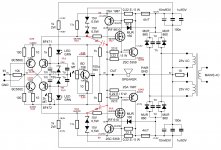
Your SSA has not even one compensating capacitor, that is why it is oscillating, so first you must add:
- 100 pF mica capacitor from input bases to GND, as close as possible to input transistors
- serial RC from output to GND, 10 Ohm/2W in series with 100 nF/100 V
- 1 uF/63 V capacitor from rails DC, after the fuses to GND
After this measures will be taken, please report the situation.

On output i a have from the beginning 10ohm+100n
I will instal 100p on input + 1uf caps on rails and report back
I will instal 100p on input + 1uf caps on rails and report back
I think i am the first to build this simple amp with BIGBT 😀
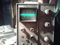
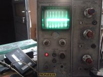
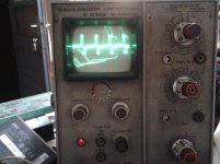
It seems that there is no way i can get rid of these oscilations
I mount 100p as close as possible to input bases, then mount 1uf+100n on bouth rails
The offset is stable at +14mV but when i tried to adjust output bias the offset jumps to 80 - 100mv and 10w resistors are very hot
Any ideas how to proceed next ?
Instructions I gave you were just a start, so proceed from there on.
Now you need to add serial RC compensation from mosfet gates to rails. Use 100 Ohm trimmer in series with 50 pF trimmer on both mosfets. For this calibration you would need oscilloscope to observe the output. Fine tuning of these trimmers will set the amp below phase margin and prevent it against instability - no oscillations.
Now you need to add serial RC compensation from mosfet gates to rails. Use 100 Ohm trimmer in series with 50 pF trimmer on both mosfets. For this calibration you would need oscilloscope to observe the output. Fine tuning of these trimmers will set the amp below phase margin and prevent it against instability - no oscillations.
hi to all
Unfortunately 2sk1058/2sj162 not availble in my city but irfp240/9240 is availble.for use this irfp what modification is Necessary for ssa?
regard
Unfortunately 2sk1058/2sj162 not availble in my city but irfp240/9240 is availble.for use this irfp what modification is Necessary for ssa?
regard
I manage borrow a o-scope
I mount 100 ohm trimmer + 47p on each gate to rails
If i adjunst trimmer from the positive rail nothing happens, if I adjust the trimmer from gate to negative rail more oscilation appear
How should i proceed next?
Both 50 pF capacitors must be trimmers otherwise calibration is nonsense. The whole aim is to set the amp's loop gain below 1 at frequency where phase shift is over 120 degrees. You can also try small capacitance from gate to GND if compensation to DC rails would be uneffective.
hi to all
Unfortunately 2sk1058/2sj162 not availble in my city but irfp240/9240 is availble.for use this irfp what modification is Necessary for ssa?
regard
Vertical mosfet's positive tempco compensation, meaning bias spreader has to have its semiconductor as a temperature sensor mounted on the main heatsink, to properly compensate temperature/output bias dependency.
Both 50 pF capacitors must be trimmers otherwise calibration is nonsense. The whole aim is to set the amp's loop gain below 1 at frequency where phase shift is over 120 degrees. You can also try small capacitance from gate to GND if compensation to DC rails would be uneffective.
I follow your advice but it's worse
Thank you very, very much for your support, but I think i will not continue because it is very difficult for a simple dyer like me with no experience resolving this unstable amplifier 🙁
Thank you very much again and good luck ! 😉
Attachments
Last edited:
I follow your advice but it's worse
Thank you very, very much for your support, but I think i will not continue because it is very difficult for a simple dyer like me with no experience resolving this unstable amplifier 🙁
Thank you very much again and good luck ! 😉
OK, according to scope plots, there's also some other problem in your circuit than just an oscillation, as so complex scope signal indicates that. Usually theres HF sine or its modulation at large. I know it's difficult for beginer to start and solve such wild amp conditions, especially if nobody built it before. This SSA version for sure can be stable, if I'll catch some spare time maybe I'll do it, but at the moment everything from me is dedicated to VSSA.
Vertical mosfet's positive tempco compensation, meaning bias spreader has to have its semiconductor as a temperature sensor mounted on the main heatsink, to properly compensate temperature/output bias dependency.
hi.your order is that bd139/140 mounted to main heatsink with irfp mosfets?
and which of ssa with dc servo or original ssa is better in sound qulity?
Grateful
...this unstable amplifier...
Hi max.
You might try these to make it stable:
1. Install two 47pF in parallel with the 1K feedback resistors, one for each.
Or,
2. Replace 1K/100R feedback network with 2K2/220R.
I can't assure but one of these tricks might help. It will be sad to see you giving up after this much progress.
shaan
Last edited:
Hi max.
You might try these to make it stable:
1. Install two 47pF in parallel with the 1K feedback resistors, one for each.
Or,
2. Replace 1K/100R feedback network with 2K2/220R.
I can't assure but one of these tricks might help. It will be sad to see you giving up after this much progress.
shaan
It is an current feedback design. So don't go for no.1!!
Place a millercap accross Basis and Collector on VAS transistor. 47pF.
Replace 1K/100R with 4K7/470R if this is stable -> 2K2/220R.
It is an current feedback design. So don't go for no.1!!
Coz doing so will make it oscillate, right?
Place a millercap accross Basis and Collector on VAS transistor. 47pF.
Where are those pins?!
Anyway, VAS compensation has been tested by him. FAILED. See just a few posts back. 😉
Replace 1K/100R with 4K7/470R if this is stable -> 2K2/220R.
Yea, Step-jump is very healthy for math exams. 😉
happy listening...
Hi shaan and sonnya 🙂
I will not give up just yet 😀
I'm waiting for Lazy Cat to get some time to review the schematic but in the meantime if you give me some help i certainly appreciate it 😉
I will try to do what you said an get back to you
Thank you shaan and sonnya
I will not give up just yet 😀
I'm waiting for Lazy Cat to get some time to review the schematic but in the meantime if you give me some help i certainly appreciate it 😉
I will try to do what you said an get back to you
Thank you shaan and sonnya
- Status
- Not open for further replies.
- Home
- Amplifiers
- Solid State
- Simple Symetrical Amplifier