This link works for me:
http://www.angelfire.com/sd/paulkemble/ssm2131pa.gif
EDIT: you got there before me
The opamp here is topologically most similar to a complimentary cascoded common-base feedback amplifier. So just like the version of SSA that matches this description.
http://www.angelfire.com/sd/paulkemble/ssm2131pa.gif
EDIT: you got there before me
The opamp here is topologically most similar to a complimentary cascoded common-base feedback amplifier. So just like the version of SSA that matches this description.
Look like there is some anti leech protection or image server lacks. Sorry.
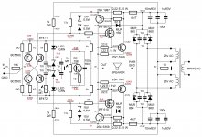
It is amusing to see the combination of both CFA( SSM2131 ) and VFA ( OP-07 ).
This said, i agree with Bonsai, all has been said about this subject, so why not concentrate on the topic: SSA design and realization ?
It is amusing to see the combination of both CFA( SSM2131 ) and VFA ( OP-07 ).
This said, i agree with Bonsai, all has been said about this subject, so why not concentrate on the topic: SSA design and realization ?
Last edited:
That's fine. I usually only reply to the threads I'm subscribed to, so I wouldn't know about the other thread. I'll get out of the way. 🙂
This is strange 😕
I think the amplifier is oscilating, everytime i whant to measure a voltave on any point of schematic the smps protection is activating, protection is set little over 9A
I tried to measure mid bridge voltage as you requested and protection is activated, same thing happened when i tried to measure voltage on IRF gate
Input of the amplifier is connected to GND
Last edited:
if can drive stk4050 a 1pc 18" subwoofer????? i already build stk4048 it is a powerfull amp my 12" speaker was burn out ,. and the 15" inch is getting hot when i over drive the power of the stk 4048 🙂
Do you have oscilloscope? Serves the purpose for cases like this. 😉
I known it's a must an osciloscope, but unfortunately i don't have one
For those, like yours trully, that know nothing about IGBTs:
IGBT tutorial: Part 1 - Selection
Cheers,
M.
IGBT tutorial: Part 1 - Selection
Cheers,
M.
I known it's a must an osciloscope, but unfortunately i don't have one
Borrow one, it is essential.

Basic rule to connect newly made DIY amp to power supply, is to connect both DC rails via serial resistors 22-33 Ohm/10 W which serves to protect the amp and output transistors from failure in a case of a wrong assembly or oscillations. This also enables to perform measurements in such abnormal conditions safely. 😉
Today I have some time to measure some voltages
First I connect to GND all the pcb traces used for normal rectifier and replace those fuses with 33ohm/10W resistors
This is good because oscilations are gone, now i can measure voltage on any point of schematic with no problem at all
Here is what i measure so far
First I connect to GND all the pcb traces used for normal rectifier and replace those fuses with 33ohm/10W resistors
This is good because oscilations are gone, now i can measure voltage on any point of schematic with no problem at all
Here is what i measure so far
Attachments
I wonder, BC550 and BC560 at Rbb~150 ohm are maybe not the best match to BF471 and BF472. Perhaps some lower Rbb transistors would further decrease the noise floor?
Just a thought.
Just a thought.
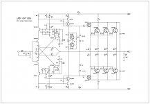
Another SSA Variation
Here's my take on LC's great amp!
Here's my take on LC's great amp!
Attachments
Last edited:
Today I have some time to measure some voltages
First I connect to GND all the pcb traces used for normal rectifier and replace those fuses with 33ohm/10W resistors
This is good because oscilations are gone, now i can measure voltage on any point of schematic with no problem at all
Here is what i measure so far
So now you have good starting ground to calibrate SSA to working conditions.
You're not so far away, indicated from your measurements values, DC offset should change in both directions and finally set it to zero. Bias through each output BJT should be 100 mA and when you'll come to this conditions, you can freely disconnect safety serial resistors and connect SSA directly to PSU via 5A/T fuses. 😉
Here's my take on LC's great amp!
WOW nice take, just needs to be realized. Any obstacles? 😎
hi dear Lc
whether you want to use such an arrangement to ssa
Is there a spot you want to correct?
Yes, according to all experiences gained from SSA, TSSA and VSSA I would change input current injection point, since that improves thermal stability into rock solid as in VSSA. 😎
That complexity of the amp would be disastrous if it would have unstable output bias and if it would walk around zero DC like a drunker, also in this way you won't need any DC servo at all. 😎
So how to make it hehe, let me see your approach and if you cannot transform and adapt it, I'll help. 😎
- Status
- Not open for further replies.
- Home
- Amplifiers
- Solid State
- Simple Symetrical Amplifier