I think the two designs are quite similar both relies on feedback as current injected in the input-device/s..The SSA is like at suspended bridged type of the Fetizilla...good to avoid the jfet though and to my experience the SSA is much more transparent than any other amplifier i have ever built.
Why do you insert the small zeetex fets around the output..??
Why do you insert the small zeetex fets around the output..??
When I added the Zetex buffers to the lateral o/p devices on my SMA it improved the stability margin and sounded considerably better so I employed the same composite MF darlingtons in my SSA design.
My o/p composite devices now have 7pF i/p capacitance ! which means the VAS can also use ZTX3310a's with 7 - 10mA which means the VAS also has i/p capacitance of 7pF !
and when I switched from the irf9610 to the ZTX3310's in the VAS that also gave a big sonic improvement.
So it was just a logical progression that made incremental improvements
p.s. I disagree about the Jfets - I think they are an asset if they can be successfully implemented
Last edited:
think the small fets is a good idea...a little problem is that they are only 60V...so that will severely limit your output swing
Actually I use zvp & zvn3310a's in my actual amps which allow 100V which for me is more than enough
I only use 3306a in spice because I had the models
Oh - I think the i/p capacitance of zvn3310a is 40pF - my mistake
I only use 3306a in spice because I had the models
Oh - I think the i/p capacitance of zvn3310a is 40pF - my mistake
Last edited:
so you can make an amplifier with +-50V swing...i guess it plenty for most use...🙂 Is that a variant of the zeetex with even more capability..Would like to put it in om mys SSA which run on 65 V
You could try ZVN / ZVP 4424's
capacitance is nowhere near as low but I think I did preferred it to irf9610 if I remember correctly.
capacitance is nowhere near as low but I think I did preferred it to irf9610 if I remember correctly.
. . . or you could go balanced working with 45V rails using the 3310a's.
Giving almost 90V swing and slewing at about 2000V / uS !
Giving almost 90V swing and slewing at about 2000V / uS !
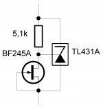
About last time problem I encounter, that the VAS temperature is hard to rise and give low bias voltage, etc. Changing heatsink only helps a little, but still have some duration on heating up. So I found another resolution, but not in audio section, so I'm wondering is it fine with this arrangement.
It is called : "emitter-feedback" bias technique or so..... I have integrated into my VAS, as a red circle area in attached picture.
If i'm not wrong, it have some kind of local feedback, so it significantly reduce the variation of current as temperature changes.
LC, could you help me see is it ok ? according to the schematic i posted, The VAS is idle at 16mA.
Hi guitar89 😉
Very nice and simple solution to boost up quiescent current conditions to stable state in a shorter time. Also figures of distortion could improved a little bit since these resistors define and linearize impedance according to the ground very precisely. To my opinion R25, R26 are close with its value, maybe more closer to 470k but R9, R11 are definitely too low, too much loading for VAS stage, try something like 22-47k. As a matter of fact you can leave these two because the most important role for stabilizing thermal conditions plays R25, R26 since the source of the quiescent current thermal fluctuations are Vbe of the input BJT's. Please try and report, hardly wait for results. 😉
Hi
I designed a version of SSA to make a close comparison to my DC linked Fetzilla design ( which I call SMA ). I think this SSA is different from previous versions
Hi mikelm 😉
Happy to see your contribution to SSA thread. Very nice mixture of BTJ and mosfets in your sch, I like it a lot. Bias current injection to SSA feedback bridge is a little more filtered out of ripple by resistor divider, also small portion of input bias current regulation is assured by this configuration. I see that thermal conditions of your VAS and output stage is self compensated since there is no Vbe multiplier or thermal diodes, nice. Hardly wait to see your SSA in action.

I think the two designs are quite similar both relies on feedback as current injected in the input-device/s..The SSA is like at suspended bridged type of the Fetizilla...good to avoid the jfet though and to my experience the SSA is much more transparent than any other amplifier i have ever built.
Hi MiiB 😉
Yes, very similar in a way of feedback current injection to the input gain devices, but I think the SSA's splitted feedback has a little more stability because it is forming a bridge where in its middle, input gain devices are locked (locked in the middle of feedback bridge) and modulated by the input signal, so very stable modulating conditions between input and feedback signals. Bridge in electronics is used for precise measurements since it has inherent differential zeroing function between middle points. So from this stability point of view, such conditions allow higher speed and higher bandwidth to achieve in a very simple form, resulting in a very transparent amplifier. 🙂
I think the two designs are quite similar both relies on feedback as current injected in the input-device/s..The SSA is like at suspended bridged type of the Fetizilla...good to avoid the jfet though and to my experience the SSA is much more transparent than any other amplifier i have ever built.
Why do you insert the small zeetex fets around the output..??
Do you mean your High Power version using 3 output pair of Lateral Mosfets and 60 volt rails?
Andrej,
You make a good point about the feedback injection stability of the SSA. However, the dual VASs tend to fight each other as they are supported from opposite rails but linked centrally at the output stage drive; this is, literally, an offseting factor.
Nonetheless, it's the best of the symmetrical designs I have seen, although the DC linking within the feedback loop to accommodate the conjoined input device bases, while masterful, does add some complication; I prefer to simply separate the bases with three diodes and use an input cap on each base, as I always prefer my amps to be AC coupled at the input.
When you sim the SSA the distortion artefacts are commendably low, and the odds almost completely absent, which is unusual for this topology as symmetrical distortions are normally produced by symmetrical designs, and these are odd order harmonics. I have not yet built it but I fully intend to, and I salute your and Alex MM's efforts, a wonderful design. The FetZilla has been quite successful, with more than 140 boards sold, so I feel your SSA would do exceptionally well as a Group Buy.
It is difficult to pin down the 'sound' of an amp, but in my view it always comes back to the topology; it has profound impact on the sonics.
Cheers,
Hugh
Hm..... seems remove those R9 & R11 only effect Quiescent Vce. So I guess I will just remove it.Hi guitar89 😉
Very nice and simple solution to boost up quiescent current conditions to stable state in a shorter time. Also figures of distortion could improved a little bit since these resistors define and linearize impedance according to the ground very precisely. To my opinion R25, R26 are close with its value, maybe more closer to 470k but R9, R11 are definitely too low, too much loading for VAS stage, try something like 22-47k. As a matter of fact you can leave these two because the most important role for stabilizing thermal conditions plays R25, R26 since the source of the quiescent current thermal fluctuations are Vbe of the input BJT's. Please try and report, hardly wait for results. 😉
I don't have those value, and Chinese New year is coming (Shops are resting), so I guess I need to wait until a week or so. (I'm also curious how will this work out, afraid an explosion will happen ^^)
Hi mikelm 😉
Happy to see your contribution to SSA thread. Very nice mixture of BTJ and mosfets in your sch, I like it a lot. Bias current injection to SSA feedback bridge is a little more filtered out of ripple by resistor divider, also small portion of input bias current regulation is assured by this configuration. I see that thermal conditions of your VAS and output stage is self compensated since there is no Vbe multiplier or thermal diodes, nice. Hardly wait to see your SSA in action.
Hi Andrej,
Many thanks for your words of encouragement. Now with extra confidence I will proceed with construction 😀
mike
Mike....
Would it not be possible to remove the mosfet driver stage completely, and just fit your mossfet-lataral compound directly..think the 100 ohm feedback can be used to set the current...
Would it not be possible to remove the mosfet driver stage completely, and just fit your mossfet-lataral compound directly..think the 100 ohm feedback can be used to set the current...
LC, it seems although it reduce the variation of DC Iq, but it also reduce variation of AC signal. SO I guess it is a local feedback, preferable to get another system which only disturb DC portion or thermal.
I'm thinking of making a heater(attached to heatsink) that will activate whenever the Iq of driver is lower than 5mA or so, is it possible ? I'm thinking to use a relay series with driver's emitter resistor, but coil within the relay would form a inductor that cut-off HF or so....
I'm thinking of making a heater(attached to heatsink) that will activate whenever the Iq of driver is lower than 5mA or so, is it possible ? I'm thinking to use a relay series with driver's emitter resistor, but coil within the relay would form a inductor that cut-off HF or so....
Indeed !Bridge in electronics is used for precise measurements since it has inherent differential zeroing function between middle points. So from this stability point of view, such conditions allow higher speed and higher bandwidth to achieve in a very simple form, resulting in a very transparent amplifier. 🙂
I'm thinking of making a heater(attached to heatsink) that will activate whenever the Iq of driver is lower than 5mA or so, is it possible ?
Not likely. 😀
Perhaps something like this would help. 🙄
Attachments
- Status
- Not open for further replies.
- Home
- Amplifiers
- Solid State
- Simple Symetrical Amplifier