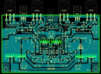
SSA BIGBT PCB rev 1.5
same PCB dressed 🙂 same size 145 mm X 86 mm and B & W file for toner transfer or photo ......😎 Thanks for the kind words addressed to me 🙂
Alex.
same PCB dressed 🙂 same size 145 mm X 86 mm and B & W file for toner transfer or photo ......😎 Thanks for the kind words addressed to me 🙂
Alex.
Attachments
Ah, not quite what I meant, but interesting nonetheless......
I think these devices would be very suitable for hard rock, I really do.
Hugh
Hard rock, anyone get the pun???
same PCB dressed 🙂 same size 145 mm X 86 mm and B & W file for toner transfer or photo ......😎 Thanks for the kind words addressed to me 🙂
Alex.
Nice Board! One question, is this rev 1.5 or 1.1? the post says 1.5, the files 1.1
I am saving all the schematics and boards.
LC....
I was thinking your basic circuit, but with lateral fets (2SK216/2SJ79 instead of the IRF 9610/610.. the laterals have only two third's of the Ciss capacitance...and also negative tempco...So I believe you can take away the VBE and instead use the simpler resistor biasing
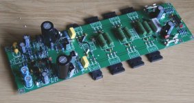
MiiB I successfully built the one that you are referring to last year in Decmeber, it sounded stunning and is currently my main listening amplifier.
Attachments
@odysseybmx414
It's written on the bottom of PCB:
Schematic Lazy Cat rev1.1
PCB by Alex MM rev1.6
@alex mm
Capacitor to the left of your logo is 1uF/63V, but you wrote 1000mF/16V.
It's written on the bottom of PCB:
Schematic Lazy Cat rev1.1
PCB by Alex MM rev1.6
@alex mm
Capacitor to the left of your logo is 1uF/63V, but you wrote 1000mF/16V.
LC....
I was thinking your basic circuit, but with lateral fets (2SK216/2SJ79 instead of the IRF 9610/610.. the laterals have only two third's of the Ciss capacitance...and also negative tempco...So I believe you can take away the VBE and instead use the simpler resistor biasing
Hi Miib
Of course IRF's can be replaced with 2SK216/2SJ79 but I am not sure if the tempco sum will be flat. If so, than SSA BIGBT Basic can be built without Vbe multiplier. Now when the board is ready you can check that in practice. 😉
I will use this board as prototype base PCB for SSA BIGBT High Performance version. 🙂
Hi Lazy Cat,
I also would make thicker traces for the power-BJT in the layout.
But I like your circuit 🙂
I had a similar circuit with IRF620/IRFP620 and i had problems with a stable BIAS.Originally Posted by MiiB View Post
LC....
I was thinking your basic circuit, but with lateral fets (2SK216/2SJ79 instead of the IRF 9610/610.. the laterals have only two third's of the Ciss capacitance...and also negative tempco...So I believe you can take away the VBE and instead use the simpler resistor biasing
I also would make thicker traces for the power-BJT in the layout.
But I like your circuit 🙂
Last edited:
Nico...
was that with my (kind of sort off folded cascode) front end,,,PCB looks really good...
M
was that with my (kind of sort off folded cascode) front end,,,PCB looks really good...
M
Member
Joined 2009
Paid Member
Very well Bigun, nice incarnation of SSA. 😎
Please feel freely to experiment further. 😉
I'm not sure I'm happy with this (Bigun's SSA) design afterall - the current through the Vbe multiplier isn't well defined and the operating points are a bit of a compromise.
Nico...
was that with my (kind of sort off folded cascode) front end,,,PCB looks really good...
M
YEP!
And you thought I only did simulations 🙂)
Last edited:
Hi Lasy Cat, i have a bunch of MJL3281/1302 laying around. I take a look at SC5359/SA1987 datasheet and they seems to me to quite near on MJL characteristics, only toshiba cob is 360pf as Onsemi cob is 600pf the reste is quite the same. Do you think they could be good candidate for SSA BIGBT?
I have a pair of 300Va 2x25V laying under bench as a pair of 200x200x40mm heatsink too. These could be a good begining for SSA BIBGT
Regards Marc
I have a pair of 300Va 2x25V laying under bench as a pair of 200x200x40mm heatsink too. These could be a good begining for SSA BIBGT
Regards Marc
Last edited:
When will we see almost made amplifier with a happy ending?😕🙁
cheers !!
I guess we all are waiting for you to built something. 😀
Otherwise read post #188 or similar but it will take you some time ... 😉
Hi Alex.
May I be bold to ask that you publish Gerber plots as well for those who are making professional boards. Just zip them up and post them with the PDFs.
The layout is very, very nice, thanks Alex.
Kind regards
Nico
May I be bold to ask that you publish Gerber plots as well for those who are making professional boards. Just zip them up and post them with the PDFs.
The layout is very, very nice, thanks Alex.
Kind regards
Nico
I wonder why this thread only have four stars? Have you all voted or is there something missing?
I wonder why this thread only have four stars? Have you all voted or is there something missing?
Yes the schematic of the real amplifier 🙂 we have enuff small amps around here, when can we see the scaled up version ...
The Big one .....

Last edited:
It would be great if Alex prepare an extra PCB for all-japan bjt devices with respecting Nico's circuit.
I wonder why all pcbs have power supply unit? Is there reason for that amplifier should be close to power unit? If it is not mandatory, PCBs should be bare in my opinion.
I wonder why all pcbs have power supply unit? Is there reason for that amplifier should be close to power unit? If it is not mandatory, PCBs should be bare in my opinion.
Last edited:
Member
Joined 2009
Paid Member
Yes the schematic of the real amplifier 🙂 we have enuff small amps around here, when can we see the scaled up version ...
The Big one .....
It's in progress....😛
Attachments
Yeeeeeow.... Now we talking , is that the PSU..........🙂
no its the dac😀
- Status
- Not open for further replies.
- Home
- Amplifiers
- Solid State
- Simple Symetrical Amplifier