Apparently, your meter is not very sensitive. You can improve the sensitivity by using a 1N34 (or similar) germanium diode to feed the meter rather than a silicon diode. Silicon diodes do not conduct until there is about .7 volts across them. Germanium diodes will conduct at a much lower voltage.
You can improve the performance even more by using four 1N34 germanium diodes in a bridge configuration to feed the meter.
Other than that suggestion, you may need to build a buffer stage to feed the meter.
It's possible to build such a stage using a transistor or two. It's easier to use an op-amp.
You can improve the performance even more by using four 1N34 germanium diodes in a bridge configuration to feed the meter.
Other than that suggestion, you may need to build a buffer stage to feed the meter.
It's possible to build such a stage using a transistor or two. It's easier to use an op-amp.
So.....I could have used the original one-trans. circuit (s.Pic) had I just fed it from the output? I think I' ĺl try the germanium diode first.Other than that suggestion, you may need to build a buffer stage to feed the meter.
It's possible to build such a stage using a transistor or two. It's easier to use an op-amp.
Happy July 4!
Attachments
P { margin-bottom: 0.08in; } I tried a 1N60 (1N34 equivalent) diode, meter registers a little earlier but the sound still needs to be turned way up. I'm going to try a bridge with 4 x Schottky's 43/46, they're low-voltage similar to 1N60. Ordered online, wating...............zzzzzzzzzzzzzzz.................
Well I've tried the diode bridge, it didn't bring any improvement, meter still only registers at high volumes. Could you possably point me towards a very simple op-amp circuit that works on 15 volts, no negative rail. I don't need complicated circuitry to calibrate or anything else, as long as it registers at a reasonable level. Much obligedOther than that suggestion, you may need to build a buffer stage to feed the meter.
It's possible to build such a stage using a transistor or two. It's easier to use an op-amp.
Last edited:
Stoppage, which meters did you get ?.
It may be that they have an internal resistor.....what is the measured resistance of your meters ?.
Dan.
It may be that they have an internal resistor.....what is the measured resistance of your meters ?.
Dan.
Stoppage, which meters did you get ?.
It may be that they have an internal resistor.....what is the measured resistance of your meters ?.
Dan.
The meters are „Mitec Joler“ see Attach.
Measured resistance is 680 Ohms
Attachments
Stoppage, which meters did you get ?.
It may be that they have an internal resistor.....what is the measured resistance of your meters ?.
Dan.
.....so I take it the measured resistance is o.k., then, or???
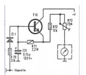
I used the schematic from Rod Elliot (VU And PPM Audio Metering).
You can control the output level to the meter.
As stated on the article you should use germanium diodes. This was the hardest part since they are almost unavailable. Buerklin has OA95.
For the meter I used the Nissei TN-73-HS. They are large, integrated led ilumination and good aspect.
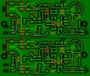
For the circuit I draw the layout of a PCB. I used the Rod Elliot circuit added with power supply regulators (78M15/79M15) and the led supply.
Works ok on my First Watt F5 Turbo. I adjust the output to 0 level at 1W. This level is ok for nomal listening.
You can control the output level to the meter.
As stated on the article you should use germanium diodes. This was the hardest part since they are almost unavailable. Buerklin has OA95.
For the meter I used the Nissei TN-73-HS. They are large, integrated led ilumination and good aspect.
For the circuit I draw the layout of a PCB. I used the Rod Elliot circuit added with power supply regulators (78M15/79M15) and the led supply.
Works ok on my First Watt F5 Turbo. I adjust the output to 0 level at 1W. This level is ok for nomal listening.
Attachments
These meters ought to be plenty sensitive, especially when connected across speaker terminals (with diode or diode bridge) in series....is there anybody out there?
Was it something I said?
Hello?
Have you tried connecting the meter directly across a 1.5V battery ?....what result did you get ?.
Dan.
Unfortunately I cannot use this op-amp as I don't have a negative supply rail. Thanks for your helpI used the schematic from Rod Elliot (VU And PPM Audio Metering).
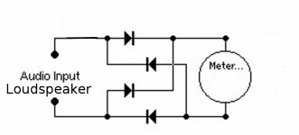
Using the circuit in Attach, the meter only registers at high volumes. Both meters battery-test perfectly fine, but I'm not using the meters as battery-testers.These meters ought to be plenty sensitive
Attachments
If you don't care about accuracy, do you even need to bother with a driver? Just get an Anders VU from farnell or whatever and stick it in??
VU Meter Circular - C450VUS | Digital Meters | Energy Meters | Panel Meters | Shunts | Current Transformers
„VU Meter Circular - C450VUS „
„A rugged and reliable Vu indicator meter suitable for a wide range of audio applications (including sound mixing desks, compressors, amplifiers, tuners and recording devices etc) used to display signal level in Volume Units when connected to suitable drive circuitry. „
yes...but you quite clearly said you don't care if it is accurate, you just want it to move around and be eye candy. It will move around without a drive circuit...
My meter won't budge without additional circuitry. Most of these cheap Ebay meters don't even have an inbuilt rectifier (they're d.c. meters).
Last edited:
I have not read the entire thread so I do not know if this has been offered to you, yet.
OK, here is what I did:
A double OP per channel, dual supply, active rectifier, time delay, and buffer.
As simple as it gets. Cannot be used for any serious measurements, pure eye candy.
Are you up to the task of converting it to single supply?
The needle moves up quickly, and down slooowly.
I salvaged my meters from an old Sony tape deck.
And to restore my honor as a serious diy-er:
This was a project a did for a friend - it is not in any of my equipment.
Attachments
- Status
- Not open for further replies.
- Home
- Source & Line
- Analog Line Level
- simple solution for VU-Meter